Avid Technology Pro Tools MTRX Studio Operation Manual
Hide thumbs
Also See for Pro Tools MTRX Studio:
- Operation manual (63 pages) ,
- Installation manual (54 pages) ,
- Operation manual (49 pages)
Table of Contents
Advertisement
Advertisement
Table of Contents

Related Manuals for Avid Technology Pro Tools MTRX Studio


Summary of Contents for Avid Technology Pro Tools MTRX Studio
- Page 1 Pro Tools ® | MTRX Studio Operation Guide...
- Page 2 Legal Notices © 2020 Avid Technology, Inc., (“Avid”), all rights reserved. This guide may not be duplicated in whole or in part without the written consent of Avid. For a current and complete list of Avid trademarks visit: www.avid.com/legal/trademarks-and-other-notices Bonjour, the Bonjour logo, and the Bonjour symbol are trademarks of Apple Computer, Inc.
-
Page 3: Table Of Contents
Contents Introduction ..................1 Pro Tools | MTRX Studio . - Page 4 Appendix A. Specifications ................52 Audio Specifications .
-
Page 5: Introduction
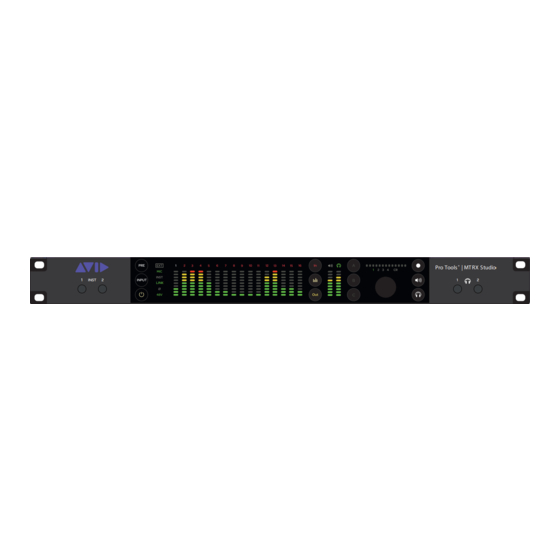
Chapter 1: Introduction Pro Tools | MTRX Studio Pro Tools ® | MT RX Studio INST LINK ® Welcome to Pro Tools | MTRX Studio. MTRX Studio is an extremely versatile multi-channel audio interface for Pro Tools | HDX and Pro Tools | HD Native systems. MTRX Studio supports 16- and 24-bit audio with sample rates of 44.1, 48, 88.2, 96, 176.4, and 192 kHz. - Page 6 Control, Routing, and Processing • Operation using DADman software—some settings can be controlled on the front panel • All settings controlled over Ethernet • 512x512 cross-point matrix • 256x32 summing (Pro | Mon) with monitor profiles • SPQ processing with 256 filters for 16 channels of speaker EQ Router Functions and Principle In addition to the AD/DA conversion and digital I/O functionality, MTRX Studio provides a powerful router matrix.
-
Page 7: Before You Start
For example, with sixteen analog input channels, each can be patched to Pro Tools Output channels and the Pro Tools input can be patched to sixteen ADAT output channels. At the same time, two channels can be patched to the analog output. It is essential that all digital signals connected to the MTRX Studio are synchronized to the same basic clock signal. -
Page 8: Resources
Resources The Avid website (www.avid.com) is your best online source for information to help you get the most out of your Avid system. Account Activation and Product Registration Activate your product to access downloads in your Avid account (or quickly create an account if you do not have one). Register your purchase online, download software, updates, documentation, and other resources. -
Page 9: Pro Tools | Mtrx Studio Operation
Pro Tools | MTRX Studio Operation Pro Tools | MTRX Studio is controlled over Ethernet by DADman software on your computer. The front panel of the unit also pro- vides indicators and controls for input settings and monitoring functions. Pro Tools | MTRX Studio Front Panel 14 15 Pro Tools ®... - Page 10 OUT button — Press to set the 16 segmented LED meters to display output levels for the selected source. Meter button — Press to cycle between sources for the 16 segmented LED meters: analog, ADAT, and Dante (1–4). The individual sources for metering are indicated by different colors in the meters and channels numbers.
-
Page 11: Instrument And Microphone Inputs 1 And 2
Instrument and Microphone Inputs 1 and 2 You can select the input (microphone or instrument) and configure the input settings for channels 1 and 2 (front panel instrument inputs or back panel mic inputs) on the front panel of MTRX Studio. To select the input source for input channels 1 and 2: If necessary, press the PRE button (4) so that it lights green. - Page 12 To switch between control layers for the Control Room monitor path: If necessary, press the PRE button so that it lights white. Press the Speaker button (15) so that CR and the speaker indicator illuminate. Press the Select button (14) to cycle through control layers 1–4. To select either Headphone 1 or Headphone 2 for control focus: If necessary, press the PRE button so that it lights white.
-
Page 13: Pro Tools | Mtrx Studio Back Panel Connections
Pro Tools | MTRX Studio Back Panel Connections Pro Tools | MTRX Studio Back Panel WC IN LOOP IN NETWORK 1 ADAT OUT MONITOR LINE OUT 1 - 8 MIC IN 1 MIC IN 2 LINE IN 1 - 8 100 - 240 VAC 50/60Hz Fuse T1AH/250 VAC Max. - Page 14 Digital I/O Connections Ethernet, RJ45 Connector, Gigabit BI_DA+ Pin 1 BI_DA– Pin 2 BI_DB+ Pin 3 BI_DC+ Pin 4 BI_DC– Pin 5 BI_DB– Pin 6 BI_DD+ Pin 7 BI_DD– Pin 8 Analog I/O Connections Analog I/O 25-pin Female D-sub Connectors MTRX Studio uses 25-pin D-sub connectors on the back panel for both analog line input (channels 1–8 and 9–16) and analog line output (channels 1–8 and 9–16).
-
Page 15: Reconfig Button
Connections for the 25-pin D-sub connector are listed in the table below. The pinning is according to the proprietary standard by Tascam. Pin number Function Pin number Function AIN/OUT 8 + AIN/OUT 8 – AIN/OUT 7 + AIN/OUT 7 – AIN/OUT 6 + AIN/OUT 6 –... - Page 16 The green LED turns on and MTRX Studio enters Recovery mode. The IP address settings of the unit are the last setting used in the unit. To switch Recovery mode to use DHCP: While the unit is in Recovery mode and the green LED is on, briefly press the Reconfig button again. ...
-
Page 17: Dadman Software
DADman Software Use DADman software to configure and control MTRX Studio over Ethernet. Assigning the IP Address for your Computer and MTRX Studio Before using DADman with MTRX Studio units on your network, you must set the network configuration for each MTRX Studio unit in your system, one at a time. -
Page 18: Dadman Configuration Files
Configure each MTRX Studio unit in turn with a unique IP address and the preferred network mask, for example 10.0.7.21 | 255.255.255.0. You can also configure IP audio network settings in this window. When you are done you can connect more than one MTRX Studio to the network, and each one appears in the DADman Device List. -
Page 19: Dadman Settings Menu
DADman Settings Menu The DADman Settings menu provides access to the Device List window, the Monitor Profile Configuration window, the MIDI Set- tings window, and lets you enable (or disable) EUCON. On Windows, it also lets you access the Options window. On Mac, use the DADman menu to access the Preferences window (which is equivalent to Options on Windows). -
Page 20: Dadman Window
DADman Window The DADman window is separated into five sections: AD, DA, Monitoring (if configured), Connections, and Configuration. Each subsection can be shown or hidden by clicking on the corresponding button in the leftmost column. DADman Window, Mon and Con sections collapsed Note that the order from left to right in which DADman shows the units are defined by the unit ID number stored in each unit. - Page 21 AD Section The AD section controls all analog inputs in the MTRX Studio: • Mic/Inst Inputs 1 and 2. • Analog Inputs (DB25) 1–8 and 9–16. AD section Any selected level slider can be adjusted with the mouse, the mouse scroll wheel, or with the Up and Down Arrows on your com- puter keyboard.
- Page 22 Line Input Channel Strips Mute Phase Invert Max dBu Level meter Level fader dB display Channel Label Line Input Channel Strip The Line input channel strips provide the following controls: Phase Invert (Ph) Click to enable (or disable) phase inversion. Click to mute (or unmute) the channel.
- Page 23 Monitor Channel Strip Mute Level fader Level meter dB display Channel Label Monitor channel strip (stereo) The Monitor channel strip provides the following controls: Mute (M) Click to mute (or unmute) the channel. Level Meter Displays the input signal level. Move to adjust the input signal level.
- Page 24 Headphone Channel Strips Mute Level meter Level fader dB display Channel Label Headphone channel strips (stereo) The Headphone channel strips provide the following controls: Mute (M) Click to mute (or unmute) the channel. Level Meter Displays the input signal level. Move to adjust the input signal level.
- Page 25 Monitor Header Display Monitor Profile label Summing Info SPQ Info Mon section: default stereo monitor profile shown Click to type a new label for the monitor profile. Monitor Profile Label Displays the summed Sources Sum fx ( n/n ) and input channels Sum inp ( n/n ). Summing Info Displays the number of SPQ channels ( SPQ ch ) used out of the total number available, and the number of SPQ EQs SPQ Info...
- Page 26 Monitor Controls MTRX Studio lets you have up to three defined monitor paths: one for the Control Room, and two for cues (Headphone Outputs 1 and 2). Delay enable Delay time Delay time display Monitor label Reference set Eq expand/collapse Channel enable Sources Output Level fader...
- Page 27 Click to expand or collapse channel view for all available sources. You can adjust the level for each source in- Sources Exp/Col dependently. Unselected sources are muted. Defined sources expanded Delay The channel delay knob controls the delay of the selected channel. This delay can be set between 0–600 ms. Outputs Under Outputs , all available monitoring outputs are listed (as configured in the Monitor Profile Configuration window).
- Page 28 Displays the monitor signal level. Output Level Meter Level Display Displays the gain adjustment to the monitor signal in dB. Output Label Click to change the label (name) for the channel. Connections Section The Connections section shows the DADman matrix for each unit in on the network. The left side of the panel for each unit and horizontal lines are inputs for the unit.
- Page 29 In the left side of the detailed matrix, there is a status indicator next to each channel: Green On a digital input, green indicates that there is a valid input and carrier. It does not indicate whether there is an audio signal present on the channel.
- Page 30 Synchronization The Synchronization pane in the General sections lets you set the following MTRX Studio parameters: Sync source , Sync out , Sync term (synchronization termination), Digi dly (in samples), Sample rate , and Adapt to . The following table shows which set- tings are available.
- Page 31 Dante Dante pane The Dante pane lets you set the following MTRX Studio parameters: Sample Rate , Dante card is a slave to the clock of the Dante network. Latency (us) , and Preferred Master . The following table shows which settings are available. Please note that DADman will only show the settings that are relevant in the given configuration.
-
Page 32: Monitor Profiles
Monitor Profiles A monitor profile is a control room or cue system using the available analog and digital I/O MTRX Studio. You can add sources, outputs, fold downs, and meters to define a monitor within DADman. A single monitor can contain multiple sources (inputs) and output sets, including stereo, surround, and expanded Atmos configurations using analog or digital I/O. - Page 33 Opening, Saving, and Closing Monitor Profile Settings Monitor Profiles can be saved and opened from the file menu. Monitor Profile files (.dmprof) store all monitor settings, EQ, and format configurations that are loaded and active in DADman. When a profile is loaded all Monitor settings are restored. You can set the Preferences (Mac) or Options (Windows) to automatically load the last saved monitor profile when DADman opens.
- Page 34 To close the current monitor profile: Choose File > Close Profile DADman saves the profile and closes it. Importing Groups and Group Formats from a Monitor Profile You can import Groups and Group formats from any monitor profile file (.dmprof) into the current monitor profile in DADman. To import groups and group formats from a monitor profile: Choose Settings >...
-
Page 35: Groups Page
Groups Page The Groups page of the Monitor Profile Configuration window lets you create and edit monitor and cue configurations for MTRX Studio. The Groups page consists of a left pane where you can add monitor and cue groups, and a right pane where you can make input and output assignments. - Page 36 Talkback Talkback is the first item in the Groups column and is always present. The source for Talkback can be any available mono input. To assign an input for Talkback: Click to highlight Talkback at the top of the Groups page of the Monitor Profile Configuration window. In the Channel column in the right pane, right-click <add channel>...
- Page 37 To remove a Monitor group: Right-click the monitor group and choose Remove monitor . Monitor Output Sets You can add multiple output sets of any format (channel width) to a Monitor group. If there are multiple Outputs , the selected Out- put in the Monitor section of DADman is used for monitoring.
- Page 38 To remove an output set: Right-click the output set and choose Remove set . Talkback Mode for Output Sets If you have assigned an input source for Talkback (see Talkback ), you can set the Talkback mode for any Monitor group Output (applies to all Outputs sets for the selected Monitor group).
- Page 39 In the right pane, right-click each channel of the selected input set and select the desired inpuy assignment from the available in- puts (such as DigiLink 1 > DigiLink 1, ch. 2 ). Assigning Right channel for selected source If desired, click in the Label column of each row and type a descriptive label. To adjust the trim on any channel, click in the Trim column for any channel and type a negative value to attenuate or a positive value (in dB) to boost the input signal for that channel.
- Page 40 External Metering You can assign one or more output sets for an external metering system (such as one from TC Electronics or DK Technologies). Assign any metering output sets to parallel assigned monitoring output sets. To add a parallel output to an external metering system: Right-click on Meters and choose Add new set or Add existing set .
-
Page 41: Fold Down Page
Fold Down Page The Fold down page lets you select preset Fold down matrices to add to monitor groups (see Fold Downs ). You can also create custom fold down matrices. For any selected fold down matrix, you can attenuate or boost inputs to ensure the optimal dynamic bal- ance in the fold down output. -
Page 42: Group Formats
Attenuating input gain of L and R source channels Fold-down and Speaker Match DADman lets you define a summing matrix (fold-down), mainly to play back a higher channel count signal as source on a speaker set with fewer channels, such as 5.1 to stereo or stereo to mono. You can match between any of the formats. Also, speaker up-match lets you play back lower channel immersive formats on more speakers in a higher channel count speaker set-up. - Page 43 Configuring Custom Speaker and Source Formats DADman lets you setup the Monitor Profile Configuration with custom speaker and source formats. Group formats are used for de- fining the channel formats for sources and outputs. This lets you connect and match the input sources to the outputs (each of which can be any of the defined formats), so left goes to left, right to right, and so on.
-
Page 44: Mom Page
The Custom Group formats can also be created or edited by selecting parameters directly in the column view as shown in the fol- lowing picture. Formats with cross-over filters for active speakers, such as left and right in an immersive set-up, can also be created when work- ing creatively with the group configurations. -
Page 45: Mtrx Studio Page
MTRX Studio Page The MTRX Studio page lets you assign the footswitch, front panel buttons A , B , and C , and the main encoder (dial) on the front panel of MTRX Studio to control talkback, monitor settings, outputs, and sources. MTRX Studio lets you assign up to 4 layers of control for the main monitor (Control Room). - Page 46 To assign a function to a switch for the selected Control Room layer or Cue: In the left pane, select Control Room 1 , 2 , 3, or 4 depending on which control layer you want, or Cue 1 or Cue 2 (for Headphone 1 and Headphone 2).
-
Page 47: Spq Processing
SPQ Processing MTRX Studio provide 256 filters and 16 channels of SPQ processing for tuning your speakers for monitoring. The EQ for all speaker channels in the control room speaker set can be edited and viewed by activating the EQ>> button. Note that the button does not enable or disable the filters, it just changes the view. - Page 48 When activating the EQ>> button the filters are activated as shown in the figure below—the white curve shows the resulting fre- quency response for the EQs on the selected channel. Configuring the EQ Channel Following are descriptions of the various EQ controls used for configuring and editing an EQ channel. Add Eq/Remove Eq Adds (or removes) an EQ to the view, both as a selection knob (named Eq 1 to 16) , and as a flat curve.
-
Page 49: Configuring Bass Management
The preceding figures show configurations for a stereo speaker set. When configuring the speaker set, select the speaker format from the preset or custom format list. The 5.1 speaker set is the selected output speaker set in the following figure. The speaker out- put sets can be configured freely in the monitor profile editor. - Page 50 When selecting Bass Management preset an editing window will appear as shown in the following picture. All speakers in the profile will have applied a high pass filter, and the summing for the SUB woofer will have the applied the low pass filter with the entered parameters.
- Page 51 When the Bass Management preset have been applied to the output set it can be viewed and further edited in the monitor profile window for the actual speaker set. As shown in the following pictures, the Bass Management filter configuration for each speaker channels is visible when scrolling the window horizontally.
-
Page 52: Controlling Mtrx Studio Preamps From Pro Tools (Mac Only)
Controlling MTRX Studio Preamps from Pro Tools (Mac Only) On Mac, you can control the two microphone preamps in MTRX Studio using the PRE controls in Pro Tools (as well as from MIDI and EUCON control surfaces). Configuring Audio MIDI Setup Use the IAC Driver in the macOS Audio MIDI Setup utility to route MIDI between Pro Tools and MTRX Studio. -
Page 53: Configure Dadman
Configure DADman Once Audio MIDI Setup is configured, setup DADman for MIDI. To configure DADman for Pro Tools PRE control of MTRX Studio units: Launch DADman software. Choose Settings > MIDI Settings . DADman MIDI Settings window Select Bus 1 for MIDI Input and Bus 2 for MIDI Output . Select Pro Tools PRE for MIDI Mode . -
Page 54: Controlling Mtrx Studio From Pro Tools (Or From A Control Surface)
To ensure that PRE controls only appear in Pro Tools for MTRX Studio Mic Inputs 1 and 2, Shift-click to select PRE channels 3–8 and press Backspace or Delete. Pro Tools I/O Setup, Mic Preamps assigned only for channels 1 and 2 Double click the Name PRE #1 and type MTRX Studio (or similar) to clearly identify MTRX Studio mic pres. - Page 55 From Pro Tools Mic Preamps view you can control the following MTRX Studio Mic Pre parameters: Mic/DI Select the microphone input setting for the corresponding Mic/Inst input channel in MTRX Studio ( Mic or DI only, Line does nothing) . ø...
-
Page 56: Appendix A. Specifications
Appendix A: Specifications Audio Specifications Microphone and Instrument Input PCM sample rates 44.1, 48, 88.2, 96, 176.4, 192 kHz Dynamic range (A) > 120 dB THD+N(A) < –108 dB @ –3dB FS Cross talk q < –120 dB Input Impedance (differential) 2 k Ohm (Mic), 1M Ohm (Inst) Max input level 21 dBu (Mic), 15 dBu (Inst) - Page 57 Analog Line and Monitor Output PCM sample rates 44.1, 48, 88.2, 96, 176.4, 192 kHz Dynamic range (A) > 118 dB THD+N(A) –110 dB @ –3 dBFS Cross talk < 120 dB Max output level Adjustable from –60 dBu to 24 dBu in steps of 0.1 dB Output Impedance <...
-
Page 58: Electrical Specifications
Electrical Specifications Power consumption 45 VA max. Input voltage 90–260 VAC 100–240 VAC Nominal, 47–63 Hz Mains fuse, mounted in IEC connector 1 A, T1AH/250V Safety compliance N 60950-1:2006 Power supply cord must be a light sheathed flexible cord according to IEC60227 (designation 60227 IEC 52) and include a protective earth conductor having a green-and-yellow insulation. -
Page 59: Appendix B. Network Fundamentals
Appendix B: Network Fundamentals The following is a basic introduction to networks and how to set them up in relation to Pro Tools | MTRX Studio. Covering the entire subject of “network” would require several hundred pages so we will focus on the “need-to-know” parts of it. What is a network? A network allows multiple devices, such as PCs, printers, and many others devices to communicate with each other. -
Page 60: Infrastructure
Finally, network cables are available as either “straight” or “crossed” cables. This nomenclature is from the “old days” when connecting two computers directly to each other. Nowadays most network devices automatically determine whether they should operate with straight or crossed connections and will adapt as necessary. Summary Only use CAT5e or CAT6 cables. - Page 61 In addition to the IP address, the device must also have a subnet mask. The subnet mask helps the device identify which other devices are on the same subnet and which are on a different subnet. Example network configuration On the left-hand side you will find the network settings of the MTRX Studio itself. On the right-hand side you will find the network set- tings for the Dante Audio over IP module or Dante Expansion card (if either is installed in the MTRX Studio).
- Page 62 Summary IP address is the address of a device in a network. Subnet mask is used to identify which devices are on the same network and which are outside the network. Default gateway is the IP address of the router, in case a connection is required outside the local network. ...
-
Page 63: Appendix C. I/O Delays
Appendix C: I/O Delays MTRX Studio Input to Output Delays The total system delay has to be large enough to accommodate for the processing latency in the unit. There is almost the same delay on all the digital I/O, and any difference is due to an inherit difference of time it takes to sync to the different signals before samples are available for time stamping. - Page 64 Technical Support (USA) Product Information Visit the Online Support Center For company and product information, www.avid.com/support visit us on the web at www.avid.com...
Need help?
Do you have a question about the Pro Tools MTRX Studio and is the answer not in the manual?
Questions and answers