Avid Technology Pro Tools MTRX Operation Manual
Ad/da converter
Hide thumbs
Also See for Pro Tools MTRX:
- Operation manual (64 pages) ,
- Installation manual (54 pages) ,
- Operation manual (49 pages)
Table of Contents
Advertisement
Quick Links
Advertisement
Table of Contents

Related Manuals for Avid Technology Pro Tools MTRX


Summary of Contents for Avid Technology Pro Tools MTRX
- Page 1 PRO TOOLS | MTRX Operation Guide...
- Page 2 Legal Notices © 2021 Avid Technology, Inc., (“Avid”), all rights reserved. This guide may not be duplicated in whole or in part without the written consent of Avid. For a current and complete list of Avid trademarks visit: www.avid.com/legal/trademarks-and-other-notices. Bonjour, the Bonjour logo, and the Bonjour symbol are trademarks of Apple Computer, Inc.
-
Page 3: Table Of Contents
Contents Chapter 1. Introduction ................1 Pro Tools | MTRX AD/DA Converter . - Page 4 Appendix C. Monitoring with MTRX and S6............. 33 Creating a Monitor Profile for Pro Tools | MTRX in DADman Software .
-
Page 5: Chapter 1. Introduction
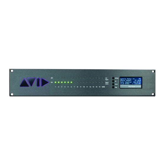
Chapter 1: Introduction Pro Tools | MTRX AD/DA Converter ™ ™ ™ ™ Welcome to Pro Tools | MTRX for Pro Tools | Ultimate software running with Pro Tools | HDX or Pro Tools | HD Native hardware. MTRX is a versatile, expandable, multi-channel audio converter and microphone preamplifier for independent simulta- neous analog-to-digital (A/D) and digital-to-analog (D/A) conversion as well as digital-to-digital (D/D) format conversion and sig- nal routing. - Page 6 Pro Tools | MTRX lets you install optional I/O expansion cards in any of the eight back panel slots that include: • Up to 48 analog channels depending on the configuration of installed Analog I/O Expansion Cards (up to 6 cards): •...
- Page 7 Sample Rate set manually Sample Rate set to external adaptation Internal external Internal sample clock Manual Sample Rate selection 44,1 Int. Clock Sample Rate 88,2 Control 174,4 Clock generator 352,8 DPLL Clock input Ext. Clock sync sources Word Clock Sample rate AES11 adapt to: Pro Tools...
-
Page 8: System Requirements And Compatibility Information
INPUTS Ch. 1-8 0 – 48 ch. Ch. 9-16 Analog inputs Ch. 41-48 Ch. 1-64 1 x MADI input Ch. 1-64 2 x optical MADI 1500 x 1500 Ch. 1-64 inputs Router Matrix Ch. 1-16 8 x AES3 input Ch. 1-32 2 x DigiLink inputs Ch. -
Page 9: Resources
The following symbols are used to highlight important information: User Tips are helpful hints for getting the most from your Pro Tools system. Important Notices include information that could affect your Pro Tools session data or the perfor- mance of your Pro Tools system. Shortcuts show you useful keyboard or mouse shortcuts. -
Page 10: Chapter 2. Pro Tools | Mtrx Operation
Chapter 2: Pro Tools | MTRX Operation Pro Tools | MTRX is controlled over Ethernet by DADman software on your computer. Some controls are also available on the front panel of the unit. Two rows of LED indicators show the AD and DA signal level, and an LCD display that shows various set- tings of the MTRX. - Page 11 Operating Buttons Setting Down Page Pushing the Setting button scrolls trough the settings rows. The > cursor marks the selected row/function. Setting Pushing the Up button scrolls up the value/setting of the selected function. Pushing the Down button scrolls down the value/setting of the selected function. Down Pushing the Page button scrolls trough the available display pages.
- Page 12 Reconfig Button The Reconfig button on the back of the MTRX should not be used during normal installation. It is generally intended as an ultimate re- covery function in case something goes wrong during programming of IP addresses, a software upgrade, or an unintended power loss. It allows the MTRX to start in various “basic”...
-
Page 13: Chapter 3. Dadman Software
Chapter 3: DADman Software Use DADman software on an Avid-qualified computer (macOS or Windows) to configure and control one or more MTRX and/or Pro Tools | MTRX Studio units over Ethernet. DADman is a channel strip–oriented, software control interface for MTRX and MTRX Studio units on your system’s network. - Page 14 Device List (Mac) Configure the MTRX (or MTRX Studio) unit in turn with a unique IP address and the preferred network mask, for example 10.0.7.21 | 255.255.255.0. You can also configure IP audio network settings (if you are using an optional Dante IP Audio expansion card or module) in this window.
-
Page 15: Dadman Menus
DADman Menus Use the DADman File and Settings menus to Save and Load Configuration files (.dms), and to access Settings on Windows. On Mac, access Preferences from the DADman menu. Saving and Loading Configuration Files When you have set up DADman as you like, you can save the configuration so it can be re-loaded later if necessary. To save a Configuration file (.dms) in DADman: Choose File >... -
Page 16: Dadman Windows
DADman Windows The DADman window is separated into the five sections: AD, DA, Monitoring (if configured), Connections, and Configuration. Each subsection can be shown or hidden by clicking on the corresponding button in the leftmost column. DADman Window Note that the order from left to right in which DADman shows the units is defined by the Unit ID number stored in each unit. The ID number for any unit can be changed by editing the Unit ID field in the Device List window ( Settings >... - Page 17 AD Section The AD section controls any Mic/Line AD and Line AD cards in the MTRX. If there are no AD cards in the MTRX, the AD section for that MTRX is empty. AD section The sliders for MIC gain can be adjusted with the mouse, the mouse scroll wheel, or with the Up and Down Arrows on your computer keyboard.
- Page 18 Monitoring Section The Monitor (Mon) section is available when the Enable monitor option is selected in the Monitor Profile Configuration Settings win- dow ( Settings > Monitor Profile ). This lets you monitor defined sources and route them to defined outputs (configured in the Monitor Profile Configuration Settings window).
- Page 19 In the Detailed matrix view, a blue circle is displayed at the top of the column if an input channel is already routed to an output channel. The circle is dark blue if an input channel that is shown in the current Detailed matrix (because the source is selected in the Overview matrix) is already routed to the output channel.
- Page 20 Synchronization The Synchronization pane in the General sections lets you set the following MTRX parameters: Source , Sampling (sample rate), Adapt to , Word Clock Out , and Sync term (synchronization termination). The following table shows which settings are available. Please note that DADman will only show the settings that are relevant in the given configuration.
- Page 21 To setup the DigiLink configuration: Click the DigiLink button and select either Pri/Exp (when using a single DigiLink Mini port to connect to your HDX or HD Native hardware and the other DigiLink port to connect to an expansion Pro Tools audio interface) or Pri/Pri (when using a both DigiLink Mini ports to connect to your HDX or HD Native hardware) from the DigiLink mode selector.
-
Page 22: Updating Pro Tools | Mtrx Firmware
Can be set to Legacy or High , but only if the sample rate is higher than 48 kHz. If the sample rate is 44.1 kHz or 48 kHz, Frame rate the Frame rate is always Legacy . In Legacy mode, the MADI Frame length is maintained and adjacent channels are “merged” into one channel. -
Page 23: Chapter 4. Network Fundamentals
Chapter 4: Network Fundamentals The following is a basic introduction to networks and how to set them up in relation to Pro Tools | MTRX. Covering the entire sub- ject of “network” would require several hundred pages so we will focus on the “need-to-know” parts of it. What is a network? A network allows multiple devices, such as PCs, printers, and many others devices to communicate with each other. -
Page 24: Infrastructure
Twisted pair cabling like CAT5e and CAT6 comes in two main varieties, solid and stranded. Solid CAT5 cable supports longer length runs and works best in fixed wiring configurations like office buildings. Stranded CAT5 and CAT6 cable, on the other hand, is more pli- able and better suited for shorter-distance, movable cabling such as on-the-fly patch cabling. - Page 25 In addition to the IP address, the device must also have a subnet mask. The subnet mask helps the device identify which other devices are on the same subnet and which are on a different subnet. Example network configuration On the left-hand side you will find the network settings of the MTRX itself. On the right-hand side you will find the network settings for the Dante Audio over IP module or Dante Expansion card (if either is installed in the MTRX).
-
Page 26: Chapter 5. Pro Tools | Mtrx Back Panel Connections
Chapter 5: Pro Tools | MTRX Back Panel Connections 100-240VAC, 50/60 Hz 100-240VAC, 50/60 Hz Max 90 VA Max 90 VA Slot Slot Slot Slot Slot Slot Slot Fuse T1AH/250VAC Fuse T1AH/250VAC Slot AES/EBU I/O 1-4 AES/EBU I/O 1-4 MADI MADI Optical I/O Optical I/O... -
Page 27: Digital I/O Connections
Digital I/O Connections MTRX Dual MADI I/O Expansion Card Optical I/O The MTRX Dual MADI I/O expansion card can be installed with one or two “Small form-factor pluggable” (SFP) transceiver modules. The SFP modules are standard types which support coaxial as well as optical and interfaces with LED or Laser diodes, and various wavelengths and fiber types. - Page 28 AES/EBU I/O 25-pin Female D-sub Connectors The top connector provides the connection for AES/EBU I/O channels 1–4. The lower connector provides the connection for AES/EBU I/O channels 5–8, providing a total of eight AES/EBU I/O channels. Connections Channel 1–4 / Channel 5–8 Below is listed the connections for the combined input and output 25-pin D-sub connector.
-
Page 29: Analog I/O Connections
Analog I/O Connections Analog I/O 25-pin Female D-sub Connectors There are four types of optional analog cards for MTRX: 8-channel Line AD Card. Pro Tools | MTRX 8 Line Pristine AD card 2-channel Mic/Line AD Card. Pro Tools | MTRX 2 Mic/Line Pristine AD card 8-channel Mic/Line AD Card. -
Page 30: Example System Configurations
Pin no Func. Pin no Func. AIN/OUT 2 + AIN/OUT 2 – AIN/OUT 1 + AIN/OUT 1 – N.C. Example System Configurations Chapter 5: Pro Tools | MTRX Back Panel Connections... -
Page 31: Appendix A. Specifications
Appendix A: Specifications Audio Specifications Analog Input Sampling, resolution 5-bit sigma/delta @ 5.645 or 6.144 MHz, 24-bit PCM PCM (DXD) sample rates 44.1, 48, 88.2, 96, 174.4, 192, 352.8, 384 kHz DSD sample rates 8224 & 5.6448 Mhz (64 & 128 fs) Dynamic range (A) >... -
Page 32: Electrical Specifications
Digital I/O and Synchronization Digital I/O formats AES/EBU, Pro Tools DigiLink Mini, Dante IP Audio/up to Supported sample rate 192 kHz, MADI/up to 384 kHz and DSD Synchronization/sample rate AES11, Word Clock, All digital inputs, Video Sync (word clock connector) / PAL, NTSC, SECAM DSD sample rates 8224 &... -
Page 33: Mechanical Specifications
Mechanical Specifications Chassis standard 19”, 2 RU Chassis depth, without connectors mounted 35.0 cm / 13.8” Chassis body width 43.5 cm / 17.2” Weight, not including I/O cards 5 kg / 11 lbs. Chassis air flow from front to rear: Environmental Specifications Operating Temperature 0–40º... -
Page 34: Appendix B. Controlling Mtrx Preamps From Pro Tools (Mac Only)
Appendix B: Controlling MTRX Preamps from Pro Tools (Mac Only) On Mac, you can control the microphone preamps for installed Pro Tools | MTRX 8-channel Mic/Line AD cards and using the PRE controls in Pro Tools (as well as from Pro Tools–compatible MIDI and EUCON control surfaces). Configuring Audio MIDI Setup Use the IAC Driver in the macOS Audio MIDI Setup utility to route MIDI between Pro Tools and MTRX units on the network. -
Page 35: Configure Pro Tools Software
Select Bus 1 MIDI Input Bus 2 MIDI Output Select Pro Tools PRE MIDI Mode Click the red button in the upper-left corner of the window to close it. Leave DADman running in the background while running Pro Tools. Configure Pro Tools Software To configure Pro Tools for PRE control of MTRX units: In Pro Tools, choose Setup >... -
Page 36: Controlling Mtrx From Pro Tools (Or From A Control Surface)
Controlling MTRX from Pro Tools (or from a Control Surface) Once configured, Pro Tools can control MTRX Mic Preamp settings on a channel-by-channel basis. Enable Mic Preamps view in either the Edit or Mix window to access these controls ( View >... -
Page 37: Appendix C. Monitoring With Mtrx And S6
Appendix C: Monitoring with MTRX and S6 Creating a Monitor Profile for Pro Tools | MTRX in DADman Software following instructions show how to create a monitor profile and configure inputs, outputs, fold-downs, and other parameters in DAD- man software. To create a new profile: Launch DADman software. - Page 38 Expand the disclosure triangle for Sources and click on New Input set . Click and hold to Rename New Input set. In the Mode column, right-click on Stereo and choose a desired input format (width) from the Set group format sub-menu.
- Page 39 In the Channel column, right-click <assign channel> and choose the type of I/O to source the input from.
- Page 40 Optionally, add input trims for each channel (ranges from –100 to +12, in 1/100 of a dB). To add additional sources, right-click on Sources and choose either Add new source or Add existing source .
- Page 41 To add an Output speaker set: Right-click on Outputs and choose Add new set . Click to expand the Outputs disclosure triangle, then click New Output Set to Rename . In the Mode column, right-click Stereo and choose a format (width) from the Set group format sub-menu.
- Page 42 In the Channel column, right-click <assign channel> and choose the desired output destination. Repeat for each channel. Optionally, modify the settings for speaker labels and trims. To add additional output sets, right-click Outputs , choose Add new set , and repeat the previous steps. Adding Fold-down To add Fold-down to an output set: Click the Fold down tab at the top of the Monitor Profile Configuration window.
- Page 43 Select the added Fold-down (such as 5.1>St ) to display and enable editing of the Fold-down equations. Optionally, you can edit the Fold-down equations. Right-click on the Fold-down to rename, remove or add additional Fold-downs. Click back on the Groups tab of the Monitor Profile Configuration window to return to the monitor settings. Right-click on Fold down and choose Add fold down to assign your newly created Fold-down to an Output set.
- Page 44 Adding a Parallel Output To add a parallel output to an external metering system (such as one from TC Electronics or DK Technologies): Right-click on Meters and choose Add new set or Add existing set . To specify Pre- or Post-Fader operation, right-click on Meters , choose Set meter mode , then choose the desired mode. Adding a Talkback Input To add a Talkback Mic input: Click to highlight Talkback at the top of the Monitor Profile Configuration window.
- Page 45 Click on Monitor and type to change its name ( Control Room ). To designate this monitor as the primary Control Room monitor for EUCON, right-click Monitor , then choose Control Room from the Set EuCon mode sub-menu. Right-click Monitor again, and choose Master from the Set monitor mode sub-menu. To add additional Monitors (such as Monitors A–D) right-click anywhere in the window and choose Add monitor .
-
Page 46: Assigning Monitor Sources On S6
Assigning Monitor Sources on S6 S6 lets you assign up to 16 sources in the Monitoring screen. To access additional sources: Navigate to the Monitoring screen. At the top of the screen, swipe the row of Sources to the left to display sources 9–16 (as available). Configuring Sources for Pro Tools | MTRX If you are using a Pro Tools | MTRX with S6, you need to first configure DADman software and then configure sources in the S6 Mon- itoring page. - Page 47 Right-click on any monitor in the profile and assign the EUCON mode to what you want to define as Control Room, Monitor A, Mon- itor B, Monitor C, and Monitor D by selecting it from the sub-menu. Assigning EUCON mode in DADman To configure sources on S6: Navigate the touchscreen to the Monitoring page (from the Home screen press Monitoring , or press the Setup 2 switch in the Mon- itor Controls section of the Master Module).
- Page 48 Tap an available source in the Source Select list to assign it to the selected input source. When first assigned, input sources are inactive (as shown in the image to the right). After assigning all your input sources you can activate them as desired by tapping in the lower third of their block in the upper Source row.
-
Page 49: Appendix D. Spq Expansion Card Operation
Appendix D: SPQ Expansion Card Operation This appendix provides an introduction to the operation of Pro Tools | MTRX with an SPQ card installed. The functions of the card are managed in DADman software. One or more SPQ cards can be installed in the MTRX. In most applications only one card is needed. The cards can be installed in any of the available card slots, and are automatically configured by the software. -
Page 50: Inspecting The Spq Card And Firmware Versions
Inspecting the SPQ Card and Firmware Versions The installed firmware version and unit configuration can be inspected in the Device list as shown below. The MTRX firmware version and the Dante module firmware version (if installed) can be seen by scrolling the list. SPQ card installed in slot 6... -
Page 51: Dadman And Monitoring
DADman and Monitoring DADman, Monitoring disabled To enable monitoring: Choose Settings > Monitor Profile Configuration Select the unit to control. Check Enable monitor... -
Page 52: General Delay
DADman adds a monitor control section in the main view as shown below. In addition, control for the general delay of the whole profile, an button, and a status indicator that displays allocated EQ resources Eq>> are shown. General Delay The delay can be set from 0 to 200 milliseconds (ms) in increments of 0.01 ms (10 microseconds). - Page 53 The EQ for all speaker channels in the control room speaker set can be edited and viewed by activating the button. Note that the EQ>> button does not enable or disable the filters, it just changes the view. EQ Filter Resources SPQ processing resources required by the EQ vary depending on configuration and sample rate.
- Page 54 When activating the button the filters are activated as shown in the figure below—the white curve shows the resulting frequency EQ>> response for the EQs on the selected channel. Configuring the EQ Channel Following are descriptions of the various EQ controls used for configuring and editing an EQ channel. Add Eq/Remove Eq Adds (or removes) an EQ to the view, both as a selection knob (named , and as a flat curve.
- Page 55 Eq Types The following EQ types are available: • Parametric EQ filter • Shelving filter: High Pass or Low Pass • Butterworth filter: High Pass or Low Pass • Linkwitch Riley: High Pass or Low Pass The preceding figures show configurations for a stereo speaker set. When configuring the speaker set, select the from speaker format the preset or custom format list.
-
Page 56: Configuring Bass Management
Configuring Bass Management The configuration of the Bass Management system is done in the Monitor Profile Configuration window. A Bass Management config- uration can be made for all speaker output sets, where the speaker format comprises one or more LFE/SUB channels. In relation to the format conventions a translation is made between what is the LFE channel in the signal source, and what are the subwoofer speakers in the speaker setup, and in that relation the mapping between LFE, Bass managed speaker channels and subwoofer speakers is also made. - Page 57 When the Bass Management preset has been applied to the output set it can be viewed and further edited in the monitor profile window for the actual speaker set. As shown in the following pictures, the Bass Management filter configuration for each speaker channels is vis- ible when scrolling the window horizontally.
-
Page 58: Configuring Custom Speaker And Source Formats
Configuring Custom Speaker and Source Formats DADman lets you setup the Monitor Profile Configuration with custom speaker and source formats. Group formats are used for defining the channel formats for sources and outputs. This lets you connect and match the input sources to the outputs (each of which can be any of the defined formats), so left goes to left, right to right, and so on. -
Page 59: Fold-Down And Speaker Match
The Custom Group formats can also be created or edited by selecting parameters directly in the column view as shown in the following picture. Formats with cross-over filters for active speakers, such as left and right in an immersive set-up, can also be created when working creatively with the group configurations. -
Page 60: Saving And Loading Monitor Profile Settings
Saving and Loading Monitor Profile Settings The monitor profile can be saved and recalled in the file menu. Note that in the preferences menu the last saved monitor profile can be set to load automatically when DADman opens. The monitor profile file stores all monitor settings, EQ and format configurations loaded and active in DADman. -
Page 61: Group Format
Group Format The available Custom group formats are referred to by name, such as “51 ch. Immersive.” Formats are available in the Custom format list when loaded. There is no allocation of I/O signal or SPQ parameters attached to the group format setting. Group Type This list has 3 categories: Source set, Output set, and Fold-down. -
Page 62: Appendix E. I/O Delays
Appendix E: I/O Delays MTRX Input to Output Delays The total system delay has to be large enough to accommodate for the processing latency in the unit. There is almost the same delay on all the digital I/O, and any difference is due to an inherit difference of time it takes to sync to the different signals before samples are available for time stamping. - Page 63 For Technical Support, visit www.avid.com/support...
Need help?
Do you have a question about the Pro Tools MTRX and is the answer not in the manual?
Questions and answers