Advertisement
Table of Contents
- 1 Unit Characteristics
- 2 Start up Screens
- 3 Buttons and Displays
- 4 Password Entry
- 5 Backlight Time
- 6 System Connect
- 7 Change Password
- 8 Ethernet Communication
- 9 Specifications
- 10 Electrical Characteristics
- 11 Mechanical Characteristics
- 12 Environmental Characteristics
- 13 Electromagnetic Compatibility
- Download this manual
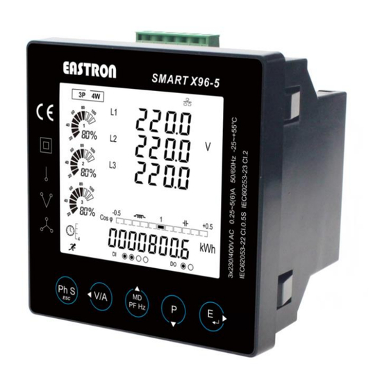
SMART X96-5
-F/G/H/I/J
MULTI-FUNCTION POWER ANALYSER
●
Multi-parameter Measurements
●
rd
Up to 63
THD and IHD
●
RS485 Modbus RTU
●
Ethernet TCP Gateway
●
Multi-tariffs
●
Digital Input/Output
●
Accuracy Class 0.5s
●
Bar Graph for Power Indication
●
Backlit LCD Display for Full Viewing Angles
●
Push-in Installation and Plug-in Connection
EASTRON SMART X96-5 F/G/H/I/J User Manual V1.
1
9
Advertisement
Table of Contents

Related Manuals for Eastron SMART X96 Series


Summary of Contents for Eastron SMART X96 Series
- Page 1 EASTRON SMART X96-5 F/G/H/I/J User Manual V1. SMART X96-5 -F/G/H/I/J MULTI-FUNCTION POWER ANALYSER ● Multi-parameter Measurements ● Up to 63 THD and IHD ● RS485 Modbus RTU ● Ethernet TCP Gateway ● Multi-tariffs ● Digital Input/Output ● Accuracy Class 0.5s ●...
-
Page 2: Unit Characteristics
EASTRON SMART X96-5 F/G/H/I/J User Manual V1. Introduction The multifunction energy analyzer SMART X96 series is a top new-generation intelligent panel meter, used not only in the electricity transmission and power distribution system, but also in the power consumption measurement and analysis in high voltage intelligent power grid. - Page 3 EASTRON SMART X96-5 F/G/H/I/J User Manual V1. value to close) ● Ethernet(TCP/IP) Communication setting: IP Address, Subnet Master, Gateway, IP port , Mode ● SOE (sequence of event) Information: 20 SOE and times ● Reset: Energy, Demand, Max.Min value, SOE, DI count, All 1.3 CT and PT...
-
Page 4: Start Up Screens
EASTRON SMART X96-5 F/G/H/I/J User Manual V1. 2.Start up screens The first screen lights all LED segments and can be used as a display LED check The second screen indicates the software version of the unit. (the left picture is just for reference) The unit performs a self-test and the screen indicates if the test is passed. -
Page 5: Buttons And Displays
EASTRON SMART X96-5 F/G/H/I/J User Manual V1. 3. Buttons and Displays 3.1 Buttons Function Buttons Click Press 2S ➢ ➢ Displays power, voltage, current and energy Automatic Scroll display ON / OFF information of each phase ➢ Exit from the menu ➢... - Page 6 EASTRON SMART X96-5 F/G/H/I/J User Manual V1. 3.2 Display Mode Screen Sequence Click button 3 Phase 4 Wire 3 Phase 3 Wire 1 Phase 2 Wire Screen Parameters Screen Parameters Screen Parameters Phase 1 – Power Phase 1 – Power Phase 1 –...
- Page 7 EASTRON SMART X96-5 F/G/H/I/J User Manual V1. Total Power Factor Total Power Factor Total Power Factor Frequency Frequency Frequency PF L1 PF L1 PF L2 PF L2 PF L3 PF L3 Max. DMD of Current Max. DMD of Current Max. DMD of Current Max.
- Page 8 EASTRON SMART X96-5 F/G/H/I/J User Manual V1. Total Active Power Total Active Power L1 Active Power Total Reactive Power Total Reactive Power L1 Reactive Power Total Apparent Power Total Apparent Power L1 Apparent Power Total kWh Total kWh Total kWh...
- Page 9 EASTRON SMART X96-5 F/G/H/I/J User Manual V1. 4. Setting-Up...
-
Page 10: Password Entry
EASTRON SMART X96-5 F/G/H/I/J User Manual V1. 4.1 Password Entry Setting-up mode is password protected, so you must enter the correct password. Default password: 1000 By firmly press the button for 2 seconds, the password screen appears. Use to set the password. If an incorrect password is entered, the display shows ERR. - Page 11 EASTRON SMART X96-5 F/G/H/I/J User Manual V1. 4.2.2 Baud rate Baud rate options: 2400 4800 9600 19200 38400 (bps). Default: 9600bps From the Communication menu, Use to select the Baud rate options. Long press to enter the selection routine. The Baud Rate setting will flash.
- Page 12 EASTRON SMART X96-5 F/G/H/I/J User Manual V1. Example shows: Set Parity: Odd *Note that Parity can only be changed to Odd when the Stop Bits is set to 1. And long press for confirmation. Press to return the communication set up menu.
- Page 13 EASTRON SMART X96-5 F/G/H/I/J User Manual V1. 4.3.1 CT2 Set secondary current input the meter Options: 5A or 1A Default CT2: 5A Long press to enter the CT2 routine. Press for 2s, the CT2 setting will flash. Use to choose CT2 with 5A or 1A.
- Page 14 EASTRON SMART X96-5 F/G/H/I/J User Manual V1. 4.4 PT PT set up menu: The PT option sets the secondary voltage of the voltage transformer (PT) that give into the meter and the PT rate between the primary voltage to the secondary voltage.
- Page 15 EASTRON SMART X96-5 F/G/H/I/J User Manual V1. 4.5 Demand This sets the period in minutes over which the current and power readings are integrated for maximum demand measurement. The options are: OFF, 5, 8, 10, 15,30, 60 minutes. From the Set-up menu, Use to select the Demand option.
- Page 16 EASTRON SMART X96-5 F/G/H/I/J User Manual V1. 4.5.1 Demand method The screen shows the Demand calculation method: Slid Options: Fix and Slid to enter Demand calculation method. Long press to enter the routine. The setting will flash. Use to choose Options. And long press for confirmation.
-
Page 17: Backlight Time
EASTRON SMART X96-5 F/G/H/I/J User Manual V1. 4.6 Time Time set up menu: sets the backlight lasting time and display scroll time. This option From the Set-up menu, Use to select the Time option. 4.6.1 Backlight time The meter provides a function to set the backlit lasting time. - Page 18 EASTRON SMART X96-5 F/G/H/I/J User Manual V1. 4.6.3 System RTC This option is to set the real time clock for the meter. to enter the real time clock option. Set the date of RTC. Left picture shows 2017-Otc-1 The format is YYYY-MM-DD press for 2s, the date setting will flash.
- Page 19 EASTRON SMART X96-5 F/G/H/I/J User Manual V1. Set the time segments and corresponding tariffs Left pictures shows: Time 01 – time segment number , range from 01 to 08 06:00 – starting time of this time segment, format : HH-MM FEE1 –...
-
Page 20: System Connect
EASTRON SMART X96-5 F/G/H/I/J User Manual V1. Example shows: The screen shows the currently selected power supply is single phase two wire 4.7.2 System connect This unit provides a function with Reverse connected current inputs correction setting. to select the correction option. -
Page 21: Change Password
EASTRON SMART X96-5 F/G/H/I/J User Manual V1. Press enter Phase 3 correction. Press for 2s, the setting will flash. Use to choose Options. And long press for confirmation. Press to return the System set up menu. 4.7.3 Change password This unit provides a function with password setting. - Page 22 EASTRON SMART X96-5 F/G/H/I/J User Manual V1. ② Escape the Setting menu. Long press for 2 secs. For example, the screen shows the currently selected Automatic Scroll display ON. Long press for 2 secs, then the screen shows the currently selected Automatic Scroll display OFF.
- Page 23 EASTRON SMART X96-5 F/G/H/I/J User Manual V1. This screen is to check the counting number of each digital inputs. By pressing the , the user can see counting numbers. Left picture shows Digital input 1, counting number is 8. By pressing , the user can see counting number of different digital inputs.
- Page 24 EASTRON SMART X96-5 F/G/H/I/J User Manual V1. This screen is to set the alarm information link to DO-1 For details , please refer to part 4.9.2 This screen is to set the digital output Type for DO-1 Left picture shows LEVE...
- Page 25 EASTRON SMART X96-5 F/G/H/I/J User Manual V1. The Alarm can be linked to the parameters below: U1, U2, U3, Unav (L-N) U12, U23, U31, Uuav (L-L) I1, I2, I3, Iav, In P1, P2, P3, P-total Q1, Q2, Q3, Q-total S1, S2, S3, S-total...
-
Page 26: Ethernet Communication
EASTRON SMART X96-5 F/G/H/I/J User Manual V1. This option is to set the Low value for DO-1 open. Left picture shows LO (Low value to Open) 170V, that means when the U1 returns to 170V, the DO-1 will open. 4.10 Ethernet Communication This menu is to set the parameter for Ethernet communication. - Page 27 EASTRON SMART X96-5 F/G/H/I/J User Manual V1. This option is to set the default Gateway This option is to set the IP port This option is to set the meter Ethernet mode SLAV = slave MAST = Master When it is set to be Master, it can works as a RS485-TCP/IP convertor.
- Page 28 EASTRON SMART X96-5 F/G/H/I/J User Manual V1. Left picture shows No.1 event By click the , the user can check other events. By pressing the button , the user can find the date and time when the event happened. 4.12 Reset This unit provides a function with reset for different information.
- Page 29 EASTRON SMART X96-5 F/G/H/I/J User Manual V1. This option is to reset the demand information. It would reset current and power demand information. This option it to reset the Max. and Min. information This option is to reset the SOE information.
-
Page 30: Specifications
EASTRON SMART X96-5 F/G/H/I/J User Manual V1. 5. Specifications Table 1 Electrical characteristics Type of measurement RMS including harmonics on three phase AC system (3P, 3P+N) 128 samples per cycle Measurement Power IEC 61557-12 Class 0.5 accuracy Active Energy IEC 62053-22 Class 0.5S, IEC 61557-12 Class 0.5 Reactive Energy ±... -
Page 31: Environmental Characteristics
EASTRON SMART X96-5 F/G/H/I/J User Manual V1. Dimensions (WxHxD) 96x96x70.3 Mounting Position Vertical Panel Thickness 1~5mm Material of meter case Self-extinguishing UL 94 V-0 Mechanical environment Environmental Characteristics Operating Temperature -25 to 55°C Storage Temperature -40 to 70°C Humidity Rating <95% RH at 50 °C (non-condensing) - Page 32 EASTRON SMART X96-5 F/G/H/I/J User Manual V1. Table 2 Models Features X96-5F X96-5G X96-5H X96-5I X96-5J Instantaneous Measurements Current ● ● ● ● ● Voltage L-N ● ● ● ● ● ● ● ● ● ● Frequency ● ● ●...
- Page 33 EASTRON SMART X96-5 F/G/H/I/J User Manual V1. CT programmable ● ● ● ● ● PT programmable ● ● ● ● ● Inputs and Outputs Digital Inputs — — Digital Outputs — — Alarms — — Communications RS485 ● ● ●...
- Page 34 EASTRON SMART X96-5 F/G/H/I/J User Manual V1. Battery Replacement The meter provides multi tariffs and RTC, it has a 3V DC battery as backup power supply. When the battery voltage is lower than 2.4V DC, the meter LCD will shows warning symbol .
- Page 35 EASTRON SMART X96-5 F/G/H/I/J User Manual V1. abiding by local regulations. Ensure all supplies are de-energized before attempting connection or other procedures. ⚫ Terminals should not be user accessible after installation and external installation provisions must be sufficient to prevent hazards under fault conditions.
- Page 36 EASTRON SMART X96-5 F/G/H/I/J User Manual V1. Smart X96-5F Smart X96-5G Smart X96-5H Smart X96-5 I/J 7.4 Mounting 7.5 Wiring Diagram RS485 / DI / DO 1P2W(L+N) 1CTs...
- Page 37 EASTRON SMART X96-5 F/G/H/I/J User Manual V1. 1P2W(L+L) 1CTs 1P3W(L+L+N) 2CTs 3P3W 2CTs 3P4W 3CTs 3P3W 2PT 2CTs 3P4W 3PT 3CTs...
- Page 38 EASTRON SMART X96-5 F/G/H/I/J User Manual V1. 3P3W 1CT Balance load 3P4W 1CT Balance load Zhejiang Eastron Electronic Co.,Ltd. No.1369,Chengnan Rd. Jiaxing, Zhejiang, 314001, China Tel: +86-573-83698881 83698882 Fax: +86-573-83698883 Email: sales@eastrongroup.com www.eastron.com.cn www.eastrongroup.com...
Need help?
Do you have a question about the SMART X96 Series and is the answer not in the manual?
Questions and answers
How do I reset a X96-5E meter as the CT 1 ratio will not change, comes up with an error. i have 13 of them in the panel is this is the only one that wont change