
Related Manuals for AZZA 366 Series


Summary of Contents for AZZA 366 Series
- Page 1 AZZA 366 Mainboard Series Cover Click Here Table Of Contents Click Here Introduction Click Here Hardware Installation Click Here BIOS Management Click Here...
- Page 2 366 Mainboard 366 Mainboard 366 Mainboard 366 Mainboard SOCKET A DDR ATX Mainboard 366X 366X- - - - AC 366X 366X 366X 366X– – – – AS 366X 366X 366X 366X– – – – AD 366X 366X Version 1.x UM-366XASD-E1 Rev 1.0V Creation Date: 26 July 2001 366 Mainboard Series...
- Page 3 USER’S NOTICE USER’S NOTICE USER’S NOTICE USER’S NOTICE Copyright This publication contains information that is protected by copyright. No part of it may be reproduced in any form or by any means or used to make any transformation adaptation without prior written permission from the copyright holders.
-
Page 4: Table Of Contents
Table Of Contents Table Of Contents Table Of Contents Table Of Contents Chapter 1:- Introduction Page 5 1.1. Overview ....................6 1.1.1. 366X Series ....................6 1.1.2. Mainboard Dimensions ................6 1.1.3. Environmental Limitations ...............6 1.2. Features and Specifications ............... 6 1.3. System Health Monitor Functions .............. 9 1.3.1. - Page 5 Table Of Contents Table Of Contents Table Of Contents Table Of Contents 2.7.4. Parallel Port Connector ................22 2.7.5. USB 1 and USB 2 Connectors ..............23 2.7.6. Audio Game Port Connector ..............23 2.8. Jumper Settings ..................23 2.8.1. JP 1: USB 1 and USB 2 Power ..............23 2.8.2.
-
Page 6: Chapter 1:- Introduction
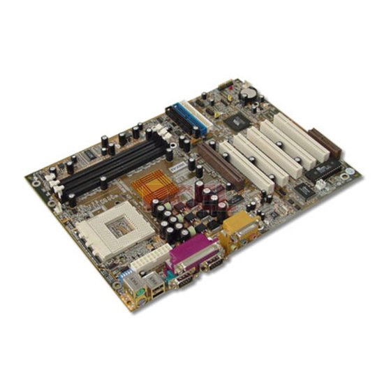
Introduction Introduction Introduction Introduction Chapter 1 - Introduction The 366X Mainboard Series:- Mainboard Layout CN 36: S/PDIF CN 21: CD Audio In CN 39:Front Audio CN 41: SCR PC 99 ATX Connector CN 16: WOL JP 1: USB CN 24: WOM 1,2 PWR CN 12: IR JP 2: KB... -
Page 7: Overview
Introduction Introduction Introduction Introduction Overview Overview Overview 1.1.1. 366X Series There are two models in this series. 366X - AC 366X - AS 366X - AD 1.1.2. Mainboard Dimensions Width 305 mm Length 220 mm 1.1.3. Environmental Limitations Operating Temperature: 10°C to 40°C (50°F to 104°F) Required Airflow: 50 linear feet per minute across the CPU... - Page 8 Introduction Introduction Introduction Introduction Expansion Slots These mainboards are equipped with five dedicated PCI slots, one CNR slot (optional for 366X-AC), which is shared with PCI 5, and one 4x AGP slot. Onboard Audio Features Supports Microsoft DirectSound/ DirectSound 3D and AC97 Full Duplex. Word Size !"""""""Data Path: 8-bit, 16-bit, 32-bit, 64-bit...
- Page 9 Introduction Introduction Introduction Introduction !"""""""CPU and chassis fan connectors. !"""""""One CD audio-in connector. !"""""""One internal audio digital interface (S/PDIF) connector (optional for 366X- AC and 366X-AS) . !"""""""One system management bus (SMB) connector. """""""""!" " """"""Front Audio connector for use with a Front Utility Panel. (optional for 366X- AC and 366X-AS) """""""""!"...
-
Page 10: System Health Monitor Functions
Introduction Introduction Introduction Introduction ATX Audio Port Front Speaker Rear Speaker Woofer and Center Speaker The surround sound feature should be used together with a Front Utility Panel. This panel brings the MIC-IN, LINE-IN and Earphones lines, together with some USB ports, to the front of the system. -
Page 11: Installation
Introduction Introduction Introduction Introduction 1.3.2. Installation To install this utility, please insert the CD into the CD-ROM drive. The auto run screen (Driver Utility) will automatically appear. Click the Hardware Monitoring button, choose the chipset, model number and the OS that is installed. Please refer to the CD “Readme” file for further installation instructions. -
Page 12: Chapter 2:- Hardware Installation
Hardware Installation Hardware Installation Hardware Installation Hardware Installation Chapter 2 - Hardware Installation Installation Checklist Expansion Slots and Sockets CPU Socket Socket A support DIMM Slots Three 168-pin DDR DIMM slots that support up to 3 GB. PCI slots Five 32 bit PCI slots: PCI 1, PCI 2, PCI 3, PCI 4 and PCI 5 AGP 4x Slot Supports 1x, 2x and 4x AGP video card CNR Slot... - Page 13 Hardware Installation Hardware Installation Hardware Installation Hardware Installation Expansion Slots, Jumpers and Internal Connectors Page Page 12 366 Mainboard Series 366 Mainboard Series Page Page 366 Mainboard Series 366 Mainboard Series...
-
Page 14: Installation Steps
Hardware Installation Hardware Installation Hardware Installation Hardware Installation Before you start Before you start installing your mainboard we strongly recommend that you use a grounded anti-static mat. We further recommend that you attach an anti-static wristband, which is grounded at the same location as the mat, to your wrist. 2.2. -
Page 15: Pci Slots
Hardware Installation Hardware Installation Hardware Installation Hardware Installation Top View of a 184-pin DDR DIMM Slot 40 pins 52 pins Important: The DIMM’s can only be fitted into the slots in one orientation. Make sure that the DIMM’s are in the correct orientation and the pins are cor- rectly aligned before you insert them. -
Page 16: Cnr (Communications Network Riser) Slot
Hardware Installation Hardware Installation Hardware Installation Hardware Installation Top view of the AGP slot 66 pins 2.3.5. CNR (Communications Network Riser) Slot (optional for 366X-AC) These slots integrate audio, modem and networking on the same card. CNR specifications support the Audio Codec 97 (AC 97) interface, LAN interfaces, USB interfaces and System Management Bus (SMBus) interfaces (used specifically to provide Plug and Play functional- ity). -
Page 17: Standard Infrared Connector
Hardware Installation Hardware Installation Hardware Installation Hardware Installation Top View of IDE 1 and IDE 2 IDE 1 PIN 1 IDE 2 PIN 1 20 pins 2.4.3. Standard Infrared Connector (optional for 366X-AC and 366X-AS) Connector: CN 12 Type: 5 pin The SIR connector supports an optional wireless transmitting and receiving module. -
Page 18: Atx Power Supply Connector
Hardware Installation Hardware Installation Hardware Installation Hardware Installation 2.4.5. ATX Power Supply Connector Connector: CN 15 Type: 20 pin block This must be connected to an ATX power supply. The plug from the power supply can only be inserted in one orientation. Make sure the pins are correctly aligned. Find the correct orientation and push the plug down firmly. -
Page 19: Cd Audio In Connector
Hardware Installation Hardware Installation Hardware Installation Hardware Installation 2.4.7. CD Audio-in Connector Connector: CN 21 Type: 4 pin un-housed This mainboard has one CD Audio-in connectors. This connector is used to connect the CD ROM audio out. Front View Of CD Audio In Connector Top View Of CD Audio In Connector Right Channel Left Channel... -
Page 20: Front Audio Connector
Type: 10 pin The front audio connector is another innovative development from AZZA. This connector is designed to be used with the Front-Utility Panel. The utility panel was developed so that a user is able to bring the speaker out, microphone in and line in connectors to the front of their PC. -
Page 21: Smb Connector
Hardware Installation Hardware Installation Hardware Installation Hardware Installation 2.4.12. SMB (System Management Bus) Connector Connector: CN 42 Type: 4 pin The SMB is a 2-wire specification which allows for communications between an external UPS or other power devices and a computer. Each 366X mainboard has a SMB connector onboard, which can be connected to other SMB devices . -
Page 22: Speaker And Power Led Connector
Hardware Installation Hardware Installation Hardware Installation Hardware Installation !" "" Press and hold the Power On Button for more than 4 seconds, the system will be powered off. Mode 2: Press and hold the Power ON button for more than 4 seconds, the system will be completely powered off. -
Page 23: External Connectors
Hardware Installation Hardware Installation Hardware Installation Hardware Installation 2.7. External Connectors Note: All the external connectors can be found at the back of the mainboard on an ATX connector shown below. CN 5: LPT CN18: Game/MIDI Port CN 7: USB 2 CN 2: PS/2 MS CN 1: PS/2 KB CN 6: USB 1 CN 3: COM 1... -
Page 24: Usb 1 And Usb 2 Connectors
Hardware Installation Hardware Installation Hardware Installation Hardware Installation .7.5. Universal Serial Bus (USB) Port 1 & 2 .7.5. Universal Serial Bus (USB) Port 1 & 2 Connector: CN 6 (USB 1)/ CN 7 (USB 2) Type: 4 pin female Two USB ports are available for connecting USB devices. The mainboard is also equipped with an expansion connector that supports two additional USB external connectors. -
Page 25: Jp2: Keyboard Power
Hardware Installation Hardware Installation Hardware Installation Hardware Installation 2.8.2. JP2: Keyboard Power Type: 3 pin Default: Pin 1 and Pin 2 Short Some keyboards may not follow standard specifications. If you find you are having prob- lems with your keyboard, change the settings on JP 2. This might help you to solve the problem. - Page 26 Hardware Installation Hardware Installation Hardware Installation Hardware Installation For example, if I set the switches in the following configuration (see diagram below): SW 1: OFF SW 2: ON SW 3: OFF SW 4: ON SW 5: ON The processing speed would be 5.5 times faster than the origi- nal CPU speed.
-
Page 27: Chapter 3:- Managing The Pc Bios
PC BIOS PC BIOS PC BIOS PC BIOS hapter 3: Managing The PC BIOS hapter 3: Managing The PC BIOS 3.1. Award BIOS CMOS Setup Utility 3.1. Award BIOS CMOS Setup Utility Once you have installed the mainboard you still need to setup the BIOS before you can run your PC. -
Page 28: Standard Cmos Setup
PC BIOS PC BIOS PC BIOS PC BIOS Navigation Keys You will notice a legend bar at the bottom of the main menu. The keys in this legend bar show you how to navigate through the setup menus. The table below lists the control keys with their corresponding functions: - Control Key Function... - Page 29 PC BIOS PC BIOS PC BIOS PC BIOS CMOS Setup Utility - Copyright ( C ) 1984 - 2001 Award Software Standard CMOS Features Date (mm : dd : yy) Thu, Jun 21 2001 Item Help Time (hh : mm : ss) 8 : 31 : 58 Menu Level ! ! ! ! ! ! ! ! IDE Primary Master...
-
Page 30: Advanced Bios Features
PC BIOS PC BIOS PC BIOS PC BIOS Monitors EGA/VGA Enhanced Graphics Adapter/Video Graphics Array. For EGA, VGA , SEGA, SVGA or PGA monitor adapters CGA 40 Color Graphics Adapter power up in 40 column mode CGA 80 Color Graphics Adapter power up in 80 column mode MONO Monochrome adapter includes high resolution monochrome adapters Halt On... - Page 31 PC BIOS PC BIOS PC BIOS PC BIOS CMOS Setup Utility - Copyright ( C ) 1984 – 2001 Award Software. Advanced BIOS Features Virus Warning [Disabled] Item Help CPU Internal Cache [Enabled] Menu Level ! ! ! ! External Cache [Enabled] CPU L2 Cache ECC Checking [Enabled]...
- Page 32 PC BIOS PC BIOS PC BIOS PC BIOS Swap Floppy Drive This field is effective only in systems with two floppy drives. When Enabled is selected physical drive B is assigned to logical drive A, and physical drive A is assigned to logical drive B.
-
Page 33: Advanced Chipset Features
PC BIOS PC BIOS PC BIOS PC BIOS TIP: Forgot your password then clear the RTC RAM If you happen to forget your password you can use Jumper 2 (JP8) to clear the pass- word by erasing the CMOS Real Time Clock (RTC) Ram. For further details on how to do this please see section 2.8.5 on page 24. - Page 34 PC BIOS PC BIOS PC BIOS PC BIOS CMOS Setup Utility - Copyright (C) 1984 - 2001 Award Software DRAM Clock/Drive Control Current FSB Frequency 100 MHz Item Help Current DRAM Frequency 133 MHz DRAM Clock [By SPD] Menu Level !! DRAM Timing [By SPD] X SDRAM Cycle Length...
- Page 35 PC BIOS PC BIOS PC BIOS PC BIOS AGP & P2P Bridge Control When you press enter the following screen will appear: CMOS Setup Utility - Copyright (C) 1984 - 2001 Award Software AGP & P2P Bridge Control AGP Aperture Size [64M] Item Help AGP Mode...
-
Page 36: Integrated Peripherals
PC BIOS PC BIOS PC BIOS PC BIOS CMOS Setup Utility - Copyright (C) 1984 - 2001 Award Software CPU & PCI Bus Control PCI1 Master 0 WS Write [Enabled] Item Help PCI2 Master 0 WS Write [Enabled] Menu Level !! PCI1 Post Write [Enabled] PCI2 Post Write... - Page 37 PC BIOS PC BIOS PC BIOS PC BIOS VIA OnChip IDE Device When you press enter the following screen will appear: CMOS Setup Utility - Copyright (C) 1984 - 2001 Award Software VIA OnChip IDE Device OnChip IDE Channel0 [Enabled] Item Help OnChip IDE Channel1 [Enabled]...
- Page 38 PC BIOS PC BIOS PC BIOS PC BIOS CMOS Setup Utility - Copyright (C) 1984 - 2001 Award Software VIA OnChip PCI Device VIA-3058 AC97 Audio [Auto] Item Help VIA-3068 MC97 Modem [Auto] Menu Level !! VIA-3058 AC97 Audio If you want to enable the on-chip audio capabilities of your system you need use the de- fault setting “Auto”.
- Page 39 PC BIOS PC BIOS PC BIOS PC BIOS UART Mode Select Your system may offer a variety of infrared modes on the second serial port. The options are Standard, HPSIR or ASKIR. RxD, TxD Active This field allows you to set the IR reception/transmission polarity as high or low. To de- termine which polarity is appropriate you must refer to the documentation for your IR peripheral.
-
Page 40: Power Management Setup
PC BIOS PC BIOS PC BIOS PC BIOS Midi Port Address This field allows you to select the I/O address for the onboard MIDI port. The default is 330. MIDI Port IRQ This field allows you to select the IRQ for the onboard MIDI port. The default is 10. Init Display First This field allows a user, with two graphics cards installed on his system, to select which graphics card will be activated first: either the PCI graphics card or the AGP graphics card. - Page 41 PC BIOS PC BIOS PC BIOS PC BIOS ACPI function This item allows you to enable/disable the Advanced Configuration and Power Manage- ment (ACPI). ACPI Suspend Type This field allows you to select the mode of the suspended state. You have two options: S1(POS) : Power On Suspend or S3(STR): Suspend to Ram.
- Page 42 PC BIOS PC BIOS PC BIOS PC BIOS Video Off Method This determines the manner in which the monitor goes blank. This selection will cause the system to turn off the vertical and hori- V/H SYNC+Blank zontal synchronization ports and write blanks to the video buffer. Blank Screen This option only writes blanks to the video buffer.
- Page 43 PC BIOS PC BIOS PC BIOS PC BIOS LPT & COM When this field is “ON” any activity from these devices, or their IRQ’s will wake up the system. HDD & FDD When this field is “ON” any activity from the HDD or the FDD will wake up the system. PCI Master When you enable the PCI Master mode, any activity from one of the listed system periph- eral devices wakes up the system.
-
Page 44: Pnp/Pci Configuration
PC BIOS PC BIOS PC BIOS PC BIOS Note: When set On, activity will neither prevent the system from going into a power management mode nor awaken it. 3.8. PNP/PCI CONFIGURATION 3.8. PNP/PCI CONFIGURATION CMOS Setup Utility - Copyright (C) 1984 - 2001 Award Software PNP OS Installed [No] Item Help... -
Page 45: Pc Health Status
PC BIOS PC BIOS PC BIOS PC BIOS Assign IRQ For VGA/USB A system’s IRQs are limited. Sometimes you may need to use more IRQ signals for your add-on cards. BIOS allows you to disable the IRQ which is supposed to be connected to the VGA and USB ports. -
Page 46: Frequency/Voltage Control
PC BIOS PC BIOS PC BIOS PC BIOS Vcore This field and the files below show you the current system voltage Shutdown Temperature When the system reaches a certain maximum temperature the system will automatically shutdown. 3.10. Frequency/Voltage Control 3.10. Frequency/Voltage Control CMOS Setup Utility - Copyright (C) 1984 - 2001 Award Software CPU Vcore Select [Default]... -
Page 47: Load Optimized Defaults
PC BIOS PC BIOS PC BIOS PC BIOS 3.11. Load Optimized Defaults 3.11. Load Optimized Defaults CMOS Setup Utility – Copyright ( C ) 1984 - 2001 Award Software ! ! ! ! Standard CMOS Features" " " " ! ! ! ! Frequency/Voltage Control ! ! ! ! Advanced BIOS Features Load Optimized Defaults ! ! ! ! Advanced Chipset Features... -
Page 48: Set User Password
PC BIOS PC BIOS PC BIOS PC BIOS The “SUPERVISOR PASSWORD” is for you to control unauthorized access to your BIOS CMOS Setup or Booting into the your PC system. The Supervisor Password option is used together with the Security Option in section 4.5. When "Setup"... -
Page 49: Save & Exit Setup/Exit Without Saving
B. When there is no password stored in the "SUPERVISOR PASSWORD" 1. When "Setup" is selected in Security Option: Users can use the "User Password" to log into the BIOS setup program, and they can change any of the BIOS settings. 2.
Need help?
Do you have a question about the 366 Series and is the answer not in the manual?
Questions and answers