
Related Manuals for ZKTeco ProEntrance Series


Summary of Contents for ZKTeco ProEntrance Series
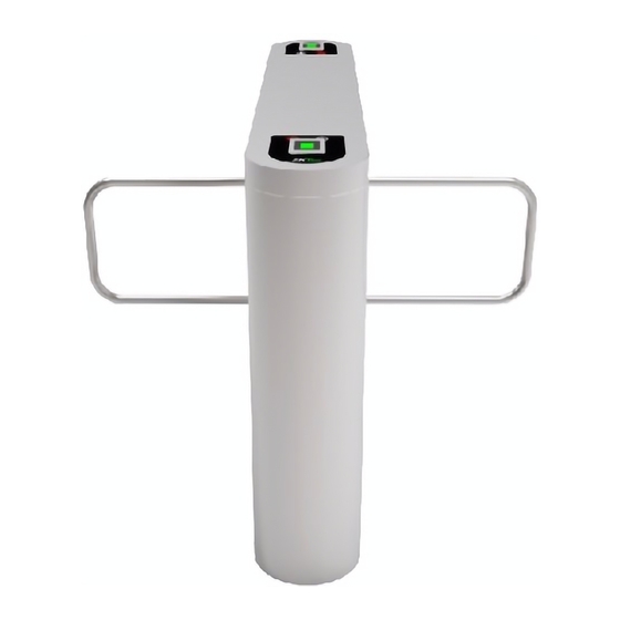
- Page 1 Quickly Installation Guide INSTALLATION GUIDE ProEntrance series Swing Barrier Applicable Models: ProEntrance SB 01RF/01FP/02RF/02FP Version: 1.0 Date: 9/2017...
- Page 2 In order to avoid the impact on communication, 220V/110V power line (high voltage) and signal line (low voltage) should be separated. The ground wire must be connected. ProEntrance series SB installation holes and cabling positions as shown in Figure 1-1 Figure 1-1...
- Page 3 Chapter 2 Installation 2.1Before the installation, it is necessary to check the device first Connect the wires between master and slave devices. Turn on the air switch to test whether the device is working properly, wait for 10 seconds for the gate to complete self-test program.
- Page 4 Chapter 3 Wiring diagram Check circuit according to the following wiring diagram: Figure 3-1 The connection of slave : Black→ GND , Green→TX, White→RX, Red→+24V The connection of master : Black→ GND , White→RX, Green→TX, Red→+24V The yellow and orange wires are prepared for access control system.
- Page 5 Chapter 4 Menu Instruction There are 4 keys on the LCD screen, including "UP”, "DOWN", "ENT", and "CANCEL". "UP" and "DEC" are reset keys, each of which has two functions. When menu operations are not used, "UP" and "DEC" can be used to open the barrier to left or right.
- Page 6 position on the right-hand side. Finally press "ENT" and the system will record this position as the right opening position.
- Page 7 Chapter 5 Common failure analysis Number Failure phenomena Analysis and solution Direction indicator no response or Check whether the connection to the roof lamp is indication is not correct. correct or not. After swipe the card there is only a Check the type setting and the 6 core connection swing arm action.
- Page 8 ZK Building, Wuhe Road, Gangtou, Bantian, Buji Town, Longgang District, Shenzhen China 518129 Tel: +86 755-89602345 Fax: +86 755-89602394 www.zkteco.com © Copyright 2014. ZKTeco Inc. ZKTeco Logo is a registered trademark of ZKTeco or a related company. All other product and company names mentioned are used for.
Need help?
Do you have a question about the ProEntrance Series and is the answer not in the manual?
Questions and answers