Nortel CallPilot 1005r Hardware Installation
Hide thumbs
Also See for CallPilot 1005r:
- Maintenance and diagnostics (206 pages) ,
- User manual (144 pages) ,
- Upgrade manual (126 pages)

Subscribe to Our Youtube Channel
Related Manuals for Nortel CallPilot 1005r


Summary of Contents for Nortel CallPilot 1005r
- Page 1 1005r Server Hardware Installation CallPilot Release 4.0 Document Number: 555-7101-228 Document Version: Standard 1.06 December 2006...
- Page 2 Nortel Networks. The process of transmitting data and call messaging between the CallPilot server and the switch or system is proprietary to Nortel Networks. Any other use of the data and the transmission process is a violation of the user license unless specifically authorized in writing by Nortel Networks prior to such use.
- Page 3 December 2006 CRYSTAL REPORTS is a trademark of Seagate Software Inc. EUDORA is a trademark of Qualcomm. eTrust and InoculateIT are trademarks of Computer Associates Think Inc. DIRECTX, EXCHANGE.NET, FRONTPAGE, INTERNET EXPLORER, LINKEXCHANGE, MICROSOFT, MICROSOFT EXCHANGE SERVER, MS-DOS, NETMEETING, OUTLOOK, POWERPOINT, VISUAL STUDIO, WINDOWS, WINDOWS MEDIA, and WINDOWS NT are trademarks of Microsoft Corporation.
- Page 4 Please be aware of the following while installing the equipment: Please use the connecting cables, power cord, and AC adaptors shipped with the equipment or specified by Nortel to be used with the equipment. If you use any other equipment, it may cause failures, malfunctioning or fire.
- Page 5 December 2006 があります。この場合には使用者が適切な対策を取るように要求されることがあ ります。 This is a Class A product based on the standard of the Voluntary Control Council for Interference by Information Technology Equipment (VCCI). If this equipment is used in a domestic environment, radio disturbance may occur, in which case, the user may be required to take corrective action. 1005r Server Hardware Installation...
- Page 6 Standard 1.06 CallPilot...
- Page 7 Publication history CallPilot 4.0, Standard 1.06 of the CallPilot December 2006 Installation and Configuration, 1005r Server Hardware Installation guide is issued for the general release. October 2006 CallPilot 4.0, Standard 1.05 of the CallPilot Installation and Configuration, 1005r Server Hardware Installation guide is issued for the general release.
- Page 8 Publication history Standard 1.06 CallPilot...
-
Page 9: Table Of Contents
To connect the external SCSI tape drive......... 49 To connect the server to the ELAN Subnet........51 To connect the server to the Nortel Server Subnet ......54 To install the software feature dongle ..........56 To connect the 1005r AC server to power........65 To start the server ................ - Page 10 Task List Standard 1.06 CallPilot...
- Page 11 Connecting the server to the Nortel Server Subnet (optional) ..54 Installing the Nortel software feature dongle ..... . . 55 Connecting the server to power Safety precautions.
- Page 12 Contents Standard 1.06 CallPilot...
-
Page 13: How To Get Help
How to get Help This section explains how to get help for Nortel products and services. Getting Help from the Nortel Web site The best way to get technical support for Nortel products is from the Nortel Technical Support Web site: www.nortel.com/support This site provides quick access to software, documentation, bulletins, and tools to address issues with Nortel products. - Page 14 To access some Nortel Technical Solutions Centers, you can use an Express Routing Code (ERC) to quickly route your call to a specialist in your Nortel product or service. To locate the ERC for your product or service, go to: www.nortel.com/erc...
-
Page 15: 1005R Server Description
C h a p t e r 2 1005r server description In this chapter 1005r Server features Valid PCI card configurations Network connectivity Supported peripheral devices Reference documents 1005r Server Hardware Installation... -
Page 16: 1005R Server Features
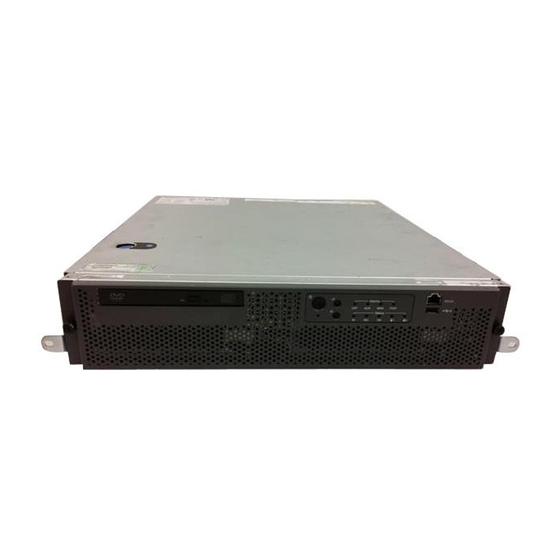
1005r server description Standard 1.06 1005r Server features Introduction The 1005r CallPilot server is a long life industrial server in a standard rack-mount 2U form factor. It utilizes dual Xeon technology and proven, reliable SCSI hard-drive technology. This section provides a general overview of the 1005r server features. RoHS compliance The 1005r server meets the requirements of the Restriction of Hazardous Substances Directive 2002/95/EC, applicable in countries affected by the... - Page 17 December 2006 1005r server description Environmental specifications Environmental condition Specification Operating temperature 5°C to 35°C (41°F to 95°F) Maximum rate of change must not ° ° exceed 10 C (50 F) per hour. Non operating (storage) -40°C to +70°C (-40°F to +158°F) temperature Non operating humidity 95% @ 23 to 40°C...
- Page 18 1005r server description Standard 1.06 Figure 1: Front panel controls Label Control or feature Label Control or feature Power switch HDD1 activity Reset switch HDD0 activity Critical alarm LED DVD/CD/CDRW LED and eject button Major alarm LED Front serial port Minor Alarm LED USB 2 Power Alarm LED...
- Page 19 December 2006 1005r server description Label Control or feature Label Control or feature ID LED Hard drive 0 pull handle NIC activity LED Hard drive 0 release lever Status LED Back panel controls and features The following diagram shows the back panel controls and features. On the right are the AC power supply banks.
- Page 20 1005r server description Standard 1.06 Label Control or feature Label Control or feature PCI full-size card brackets. Video connector Numbered (1, 2, 3) from top to bottom. Power Supply 1 USB 1 Power Supply 2 USB 0 PS/2 Mouse and Keyboard Server management LAN connectors port...
- Page 21 December 2006 1005r server description PCI riser assembly The PCI riser assembly holds the PCI add-in cards; MPB96, RAID and dual Network Interface Card (NIC). For more information about your configuration, see “Valid PCI card configurations” on page 24. The following diagram shows the PCI riser held above the server.
- Page 22 1005r server description Standard 1.06 The following picture shows the PCI riser assembly when removed from the 1005r chassis. The PCI riser assembly is shown turned over with low-profile and full-size cards installed. Figure 4: PCI riser card (turned over) CallPilot...
- Page 23 December 2006 1005r server description CAUTION Risk of physical equipment damage Remove the 1005r from the rack, and place it on a solid surface when replacing or adding cards. The PCI riser assembly requires considerable force when inserting it into the connector, and physical damage can result if the assembly is not properly aligned.
-
Page 24: Valid Pci Card Configurations
“1005r PCI card slot configurations” on page Note: Your server configuration depends on what was ordered from Nortel. Therefore, your server may not have all of the slots populated. When looking at the server from the rear (see “Back panel controls and features”... - Page 25 December 2006 1005r server description Table 1: 1005r PCI card slot configurations Meridian 1 Card slot Slot Succession Configuration type number Position Card type 1000 Single MPB96 Full size FS_PCI-1 top MPB96 MGate 1, 2, 3 FS_PCI-2 middle Not used FS_PCI-3 bottom Not used LP_PCI-1 top...
-
Page 26: Network Connectivity
1005r server description Standard 1.06 Network connectivity Introduction This section describes how the 1005r server can be integrated into your network. The integration depends on the type of switch you are using. ATTENTION To secure the CallPilot server from unauthorized access, ensure that the CallPilot network is inside your organization’s firewall. - Page 27 December 2006 1005r server description Sample network setup: Meridian 1 The following diagram shows a CallPilot server sample network setup with a Meridian 1 switch. The Meridian 1 switch can be one of the following: Option 11C or Option 11C Mini Option 51C Option 61C Options 81 and 81C...
- Page 28 1005r server description Standard 1.06 Sample network setup: Succession 1000 The following diagram shows a CallPilot server network setup with a Succession 1000 system. Web-enabled Desktop i2004 CallPilot client Internet administrative phonesets Telephony LAN/Customer LAN (10/100BaseT or 100BaseT) Succession Router or Internet SCSI tape drive 1000 Media...
- Page 29 NIC labeled LAN2 on the back of the server to the ELAN Subnet. For information about the purpose and requirements of the ELAN, see the Planning and Engineering Guide (555-7101-101). The second NIC, labeled LAN1 can be connected to the Nortel Server Subnet. 1005r Server Hardware Installation...
- Page 30 Standard 1.06 This optional NIC is required only for Meridian 1 or Succession 1000 systems that require a Nortel Server Subnet connection (in addition to the ELAN Subnet connection). The Nortel Server Subnet provides data connectivity between desktop and web messaging clients, Web-enabled administrative PCs, and the CallPilot server.
-
Page 31: Supported Peripheral Devices
1005r server and the Meridian 1 switch or Succession 1000 system. The customer can supply a hub or switch from third-party vendors or from Nortel. Since the hub is an external device, it requires an AC power source. - Page 32 1005r server description Standard 1.06 Device Description Tape drive Use an external SCSI tape drive to back up your system. The Tandberg SLR 75 is provided with your system. CallPilot...
- Page 33 December 2006 1005r server description Reference documents Fundamentals CallPilot Fundamentals Guide (555-7101-010) Planning and Engineering Planning and Engineering Guide (555-7101-101) Network Planning Guide (555-7101-102) Data Networking for Voice over IP Guide (553-3001-160) Installation and Configuration Upgrade and Platform Migration Guide (555-7101-207) Installation and Configuration Task List Guide (555-7101-210) Server Installation Guides 201i Server Hardware Installation Guide (555-7101-220)
- Page 34 1005r server description Standard 1.06 CallPilot...
-
Page 35: Preparing For Installation
C h a p t e r 3 Preparing for installation In this chapter Installation overview Unpacking the 1005r server Removing the front bezel 1005r Server Hardware Installation... -
Page 36: Installation Overview
Preparing for installation Standard 1.06 Installation overview Introduction This section provides an overview of the steps required to install the 1005r server and peripheral devices. Installation checklist The following checklist identifies the tasks that must be performed when installing the CallPilot server. For detailed instructions, see Chapter 4, “Installing the server.”... - Page 37 10 m (33 ft.) away from the 1005r server. Shielded Ethernet cables must be used. ❒ Note: If you are connecting the optional Nortel Server Subnet, do not power up unless your antivirus programs and Nortel security updates are installed first.
- Page 38 Preparing for installation Standard 1.06 Conventions for warnings You could encounter the following types of warnings in this guide. Do not ignore them. DANGER Risk of electric shock Warns you of an immediate electrical hazard which, if not avoided, can result in shock, serious injury, or death. WARNING Risk of personal injury Warns you of a situation in which you can be injured if...
-
Page 39: To Unpack The Equipment
December 2006 Preparing for installation Unpacking the 1005r server Introduction Follow this procedure to unpack the server and peripherals. WARNING Risk of personal injury The 1005r CallPilot server weighs approximately 20 kg (44 lb) when it is shipped from manufacturing. To prevent personal injury, have someone help you to unpack and position the server. - Page 40 Preparing for installation Standard 1.06 Save all packing materials and cartons in case you must return any equipment to the carrier. What is next? Remove the front bezel cover so that you can inspect the front panel of the server. See “Removing the front bezel”...
-
Page 41: To Remove The Front Bezel
December 2006 Preparing for installation Removing the front bezel Introduction To access the hard drives on the front panel, you must remove the front bezel. The front bezel covers the electrostatic discharge (ESD) connection, both hard drives, and the DVD/CD/CDRW drive pull handle. The control panel, USB port 2, and the front comm 2 serial port connection are not covered by the front bezel. - Page 42 Preparing for installation Standard 1.06 Loosen the two black captive fasteners on either side of the front bezel. Pull the front bezel off the front panel by the captive fasteners. Do not touch components on the front panel without ESD protection.
-
Page 43: Installing The Server And Peripheral Devices
In this chapter Installing the server Inspecting the modem Connecting peripherals to the server Connecting the server to the ELAN Subnet Connecting the server to the Nortel Server Subnet (optional) Installing the Nortel software feature dongle 1005r Server Hardware Installation... -
Page 44: To Install The Server
61 cm (24 in.) between the mounting posts. Check the rack you are using and ensure that the Nortel supplied server rack rails are suitable for your specific installation requirements. For depths greater than 61 cm (24 in.), Nortel recommends that you purchase a third-party rack shelf that can safely hold up to 30 kg (66 lb). -
Page 45: To Replace The Front Bezel
December 2006 Installing the server and peripheral devices To replace the front bezel When the CallPilot server is in its final location, replace the front bezel. Align the front bezel with the captive fasteners on either side of the front bezel with the threaded holes in the front panel. Tighten the captive fasteners by hand. -
Page 46: Inspecting The Modem
Inspecting the modem Introduction You require a modem to support remote dial-up access to the CallPilot server. Nortel technical support also connects to your CallPilot server for troubleshooting purposes. Nortel connects to your server only when you request technical assistance. -
Page 47: Connecting Peripherals To The Server
December 2006 Installing the server and peripheral devices Connecting peripherals to the server Rear panel connectors The following diagram shows the connectors on the rear panel. Label Control or feature Label Control or feature DB15 Telco alarm RJ45 NIC 1 connector connector (not used) PCI low-profile card RJ45 NIC 2 connector... -
Page 48: To Connect The Mouse, Keyboard, And Monitor To The Server
Installing the server and peripheral devices Standard 1.06 Label Control or feature Label Control or feature PS/2 Mouse and Keyboard Server management LAN connectors port Rear comm 2 serial port External SCSI tape drive connector connector To connect the mouse, keyboard, and monitor to the server Place the monitor, keyboard, and mouse in the same location as the server. -
Page 49: To Connect The External Scsi Tape Drive
December 2006 Installing the server and peripheral devices Connect one end of the USB cable into the modem. Connect the other end of the USB cable into either USB port 1 on the rear panel (long term) or USB port 2 on the front panel (short term). - Page 50 Installing the server and peripheral devices Standard 1.06 Figure 5: SLR75 tape drive installed on 1005r The tape drive is plug-and-play and the required drivers are already installed on your system. You must run the device scan initiation in device manager to detect the drive.
-
Page 51: To Connect The Server To The Elan Subnet
December 2006 Installing the server and peripheral devices Connecting the server to the ELAN Subnet Introduction Connect the CallPilot server to the Meridian 1 switch or Succession 1000 system using the ELAN Subnet. ATTENTION For important considerations about using the ELAN Subnet in your network, see the Planning and Engineering Guide (555-7101-101). - Page 52 Installing the server and peripheral devices Standard 1.06 At the switch, connect the ELAN network cable to the ELAN Ethernet interface. Complete the connection from the transceiver to the switch. DANGER Risk of fire hazard Do not install a Media Access Unit (MAU) in ducts, plenums, or other spaces used for environmental air.
- Page 53 Installing the server and peripheral devices What is next? IF the server is THEN connected to a Nortel Server continue with page Subnet not connected to a Nortel Server continue with installing the software Subnet feature dongle. See page 1005r Server Hardware Installation...
-
Page 54: To Connect The Server To The Nortel Server Subnet
Introduction This section provides instructions to connect the server to the Nortel Server Subnet. Note: The Nortel Server Subnet is optional. However, it is required to support desktop and web messaging users. ATTENTION To comply with EMC radiation requirements, a Class A hub must be located 10 m (33 ft.) away from the 1005r... -
Page 55: Installing The Nortel Software Feature Dongle
Introduction The software feature key is a security device that stores the unique serial number of the server. The feature key is embedded in the Nortel software feature dongle, which plugs into USB port 0 on the rear panel. The following diagram shows the dongle plugged into the back panel of the server: Figure 6: Dongle installed on the server. -
Page 56: To Install The Software Feature Dongle
Installing the server and peripheral devices Standard 1.06 To install the software feature dongle Ensure that there is nothing plugged into USB port 0 on the rear panel. If the software feature key is not preinstalled in the dongle, insert it into the software feature slot on the dongle. - Page 57 December 2006 Installing the server and peripheral devices Figure 8: Installing the. feature key. Plug the dongle into USB port 0 on the rear panel of the server. Note: Due to system driver allocations, the dongle must be installed in USB port 0. What is next? Continue with “Connecting the server to power”...
- Page 58 Installing the server and peripheral devices Standard 1.06 CallPilot...
-
Page 59: Connecting The Server To Power
C h a p t e r 5 Connecting the server to power In this chapter Safety precautions Locating the power supply modules About the power supply module Connecting the server to power 1005r Server Hardware Installation... -
Page 60: Safety Precautions
Connecting the server to power Standard 1.06 Safety precautions Equipment handling guidelines External power equipment, such as an uninterruptible power supply (UPS), is usually very heavy. This equipment requires special handling procedures and additional personnel for unloading and installation. Be aware of weight distribution, and prevent the equipment room floor from being overly stressed. -
Page 61: Locating The Power Supply Modules
December 2006 Connecting the server to power Locating the power supply modules Introduction Both AC power supply modules are installed prior to shipping.The following diagram shows the location of the power supply modules in the rear panel (D and E): Figure 9: 1005r rear panel About the power supply module After you power up the server (later in this guide), the power supply... - Page 62 Connecting the server to power Standard 1.06 In rack-mount server installations, ensure the CallPilot server chassis and equipment racks are isolated from other foreign sources of ground. Acceptable isolation methods include: isolation pads, grommeted washers, chassis side-rail strips, and nonconducting washers.
-
Page 63: Connecting The Server To Power
December 2006 Connecting the server to power Connecting the server to power Before you begin Ensure that proper power and grounding are available for all the power outlets serving the CallPilot server and its associated peripherals. Power for these devices must be wired and fused independently of all other receptacles, and referenced to the same ground as the PBX system. - Page 64 Connecting the server to power Standard 1.06 Figure 10: 1005r server in a network. CallPilot server RJ-45 RJ-45 SCSI tape Mouse Monitor ELAN hub CLAN hub Modem drive (M1 or (optional) Keyboard Succession 1000 only) power power power power power source G250018 CallPilot...
-
Page 65: To Connect The 1005R Ac Server To Power
December 2006 Connecting the server to power To connect the 1005r AC server to power WARNING Risk of personal injury, risk of hardware failure The power outlets used by the CallPilot server and its peripheral devices must be connected to the same single-point ground reference as the one used by the switch with MGate cards connected to the CallPilot server. - Page 66 Connecting the server to power Standard 1.06 Use the wizard to configure your system. For further details, see the Installation and Configuration Task List (555-7101-210). CallPilot...
-
Page 67: Emc Emission Level Protection For The 1005R Server
To lower the EMC emission level, ferrite cores are installed with one loop (see the following diagram) on the following external cables: Ferrite Core (TDK and part number ZCAT3035-1330)—for the triple DS30X I/O cable (Nortel and part number NTRH2014E6). There are three ferrite cores at each end of the cable. CAUTION Risk of equipment damage The ferrite cores are preinstalled on the provided cables. - Page 68 EMC emission level protection for the 1005r Server Standard 1.06 Figure 11: Ferrite cores secured to an external cable The ferrite cores are secured to the appropriate cable with plastic enclosure clips. Tie wraps are added to the cable loop. CallPilot...
-
Page 69: Index
Index Numerics 1005r server devices, peripheral back panel Ethernet hub dimensions and weight keyboard ELAN modem connection, establishing monitor environmental specifications mouse front bezel diagram removing 1005r server in network replacing back panel front panel slot locations installing connection PCI card slots network, CS 1000 and CallPilot server PCI riser assembly peripheral devices, supported... - Page 70 Nortel Server Subnet diagram connecting the server front bezel removing replacing part number Ethernet hub keyboard illustration modem TLAN...
- Page 71 December 2006 Index rack power and grounding protocols, supported network warnings, conventions weight, 1005r server rack power and grounding remote access connectivity safety information SCSI tape drive connecting to the server serial number of the server server connecting peripherals environmental specifications power connection serial number slot...
- Page 72 Index Standard 1.06 CallPilot...
- Page 74 The information in this document is proprietary to Nortel Networks. *Nortel Networks, the Nortel Networks logo, and the Globemark are trademarks of Nortel Networks. *Microsoft, MS, MS-DOS, Windows, and Windows NT are registered trademarks of Microsoft Corporation.
Need help?
Do you have a question about the CallPilot 1005r and is the answer not in the manual?
Questions and answers