Table of Contents
Advertisement
Quick Links
Advertisement
Table of Contents

Related Manuals for Synesso MVP Series


Summary of Contents for Synesso MVP Series
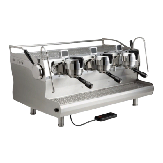
- Page 1 MVP & MVP HYDRA TECHNICAL MANUAL VERSION 2020.1 Last update: September 2020 3 Group MVP 5610 4th Ave S. / Seattle, WA 98108—USA Tel: +1 206 764 0600 / Fax: +1 206 764 0601 Ordering Parts: parts@synesso.com Information: info@synesso.com www.synesso.com...
-
Page 2: Table Of Contents
TABLE OF CONTENTS Menu Level 2 - Settings 51-58 Introduction Access Menu Level 2 Safety Warnings 4 -5 Save Lockout Start Up Screen, Serial #, Software Ver. Programs, Activate/Deactivate List of Tools and Supplies Temperature, Fahrenheit & Celsius Warranty & Water Standards Line Pressure Boost System 52-53 Plumbing Requirements... -
Page 3: Introduction
This manual applies to Synesso™ models: MVP and MVP Hydra machines. The MVP machines can be con- figured to operate any group head as manual, manual with a program and full volumetric with a program that includes adjustable total water volume. -
Page 4: Safety Warnings
The hot water mix valve can be adjusted to deliver water as hot as 212°F (100°C), which can cause severe burns: please use caution when activating this water source. Safety Label Locations: Synesso™ complies with UL regulations by posting the following labels on its machines: WARNING WARNING: Disconnect from... - Page 5 BREW & STEAM TANK SAFETY Safety Precautions: Espresso machines have numerous potential hazards, and it is of paramount importance to Synesso™ that people servicing our machines take all necessary precautions to ensure their personal safety. When work- ing on the machine’s boilers (unless otherwise instructed in the directions): •...
-
Page 6: Start Up Screen, Serial #, Software Ver
14- is the year it was built (14 is the year 2014) & 2030 is the machine sequence number RECOMMENDED TOOLS & SUPPLIES Tools and recommended items required to fully diagnose, service and maintain Synesso espresso machines. • Multi Meter – reads volts, amps and ohms •... -
Page 7: Warranty & Water Standards
24 months from the original date of shipment. Synesso will make a good faith effort for prompt correction or other adjustment with respect to any non-wearing part that proves to be defective within the limited warranty period. - Page 8 Synesso’s liability is limited to the purchase price of the product and shall not be held liable for damages that extend beyond the product itself. Synesso’s liability of consequential, incidental damages, indirect or direct damages for personal injury, inability to properly use this product, loss of business profits or interruption to business is expressly disclaimed.
-
Page 9: Plumbing Requirements
Turn incoming water ON and check for leaks. Synesso machines require a minimum of 50 PSI (3.5 bar) of line pressure at 30 gal (120 L) per hour to have the auto-fill system for the steam tank functioning properly. Please ensure that the incoming water meets this requirement or contact Synesso for alternative methods of boosting water pressure. -
Page 10: Electrical Requirements
ELECTRICAL REQUIREMENTS All Synesso™ machines are rated to operate on 220 VAC with a 50 or 60 Hz frequency, single phase. Ma- chines will operate between 208 V and 240 V. Listed amp ratings are all measured at 220 V. Incorrect voltage can cause malfunction or damage to the ma- chine. -
Page 11: Installation
INSTALLATION & WORK STATION To obtain the 2 Year Plus Warranty, an authorized or certified espresso service representa- tive must perform the installation of this espresso machine. Site Preparation - See Diagram on page 12 The machine must be placed on a level horizontal surface that can be easily cleaned and is capable of sus- taining a minimum of 300 lbs. - Page 12 INSTALLATION DIMENSIONS...
-
Page 13: Model Specific Installation
MVP Hydra Pump Assembly with Bypass Model Specific Color Coding: Depending on the MVP Series model and number of groups, color-coded zip ties will be present on the wa- ter lines, electrical cords, and pump/motors. The colors are as follows: •... - Page 14 MODEL SPECIFIC REQUIREMENTS & INSTALLATION MVP Hydra Pump/Motor Wiring: For the MVP Hydra machines, the power cord to the pump/motor is connected within the bypass box. To connect the power cord: Insert the color coded pump cable into the opening of the matching bypass box and attach the wires to the terminal as shown in the picture to the left: green wires stacked on the ground bolt, white matches across to white/red on ter-...
- Page 15 MODEL SPECIFIC REQUIREMENTS & INSTALLATION Model Specific Plumbing Requirements: Both the MVP Hydra and MVP machines require one incoming water source. For the MVP Hydra machines, the incoming water passes through a manifold (this was part of the line pressure regulator) from xx-xx- 3854 each pump has a regulator.
-
Page 16: Side Panel Removal
MVP & MVP HYDRA - 2 PIECE SIDE PANELS This side panel is shown with the trim plates removed, to display the way the lower panel interlocks with the upper panel. When removing the Lower Side Panel from the espresso machine: •... -
Page 17: Start Up
START UP Start-Up Instructions 1. Connect the water lines and the drain hose. Turn the water ON. Water will begin to flow into the brew groups. 2. Ensure the heating element breaker switch is in the OFF position. Then switch the red electronics On/Off switch to the ON position. - Page 18 Once the desired pressure is reached, retighten the lock nut and turn off the group. 7. Please allow at least 30 minutes of “warm up” time before using your Synesso™ espresso machine to brew shots or steam milk. The steam gauge (the left hand gauge) should read a minimum of 1.1 bar before the steam tank is at an operational pressure.
-
Page 19: Stage Pressure Ramping Setup
4 STAGE PRESSURE RAMPING SETUP - MVP HYDRA MVP Hydra Bypass Pump and Motor Assembly MVP Hydras come with a bypass pump and mo- Pressure Regulator for tor assembly that allow for four-stage pressure Preinfusion Pressure ramping. The shot begins with preinfusion. Low pressure water saturates the puck, swelling it to reduce channeling. -
Page 20: Operation
1. Select the desired spout and basket configuration. Single, double and bottomless portafilters are available through Synesso™. The single spout portafilter is used with a single (7g) basket to brew a single shot. The double spouted and bottomless portafilters can be used with double (14g) or triple (18g or 21g) baskets to brew double or triple shots. - Page 21 OPERATION Brewing in M (Manual) Mode: Manual mode allows the user to cycle through each stage of pressure profiling, from the start of the shot to the end, manually. To brew a shot in M mode, follow the instructions below: 1.
- Page 22 OPERATION Brew Pressure Graph 2 Bars: Bypass Pressure 3 Bars: Pump Pressure 2 Bars: Bypass Pressure 1 Bar: Low Pressure Ramp Up Full Pressure Brew (9 bar) Ramp Down Preinfusion Using the Save Function: The MVP and MVP Hydra are able to store the last brewing function performed to a temporary memory. The save function can then be utilized to save the last brewing function performed as a recipe to any of the 6 programs on any or all of the groups.
- Page 23 OPERATION Using the Save Function Continued... Note: The following functions do not change the memory of the last brewing function: • Turning on save mode (hold any brew group handle right for 2.5 seconds) • Shifting thru the 6 available programs (momentary presses of the brew group handle to the right) •...
- Page 24 Note: Although Synesso™ steam wands are made with a proprietary double-walled process that helps to keep the outer wall cooler, the tip and base can become very hot and caution must be used.
-
Page 25: Hydraulic System
HYDRAULIC SYSTEM Overview The hydraulic system in the Synesso™ is comprised of all parts through which water flows starting with where it enters the machine from the water treatment/filtration system. This chapter will detail the flow of water and some of the associated electrical components. - Page 26 HYDRAULIC SCHEMATIC - MVP...
- Page 27 HYDRAULIC SCHEMATIC- MVP HYDRA...
-
Page 28: Hydraulic System Diagrams
Clockwise to INCREASE pressure Counterclockwise to DECREASE pressure Synesso uses a Marathon carbonator pump motor to power the pump. CE machines use a 50 Hz Fluid-O-Tech pump motor. MVP vs MVP Hydra Pump Configurations: MVP machines have a single pump/motor for the machine. The pump has the dual inlet configuration as shown. -
Page 29: Water Inlet (Right Side)
HYDRAULIC SYSTEM MAJOR COMPONENTS OF THE WATER INLET SYSTEM (Right Side) MVP Hydra 3 Group, Water Inlet (Right Side) Brew Gauge Ball Valve, Steam Valve Shutoff Pressure Relief Valve under the Vacuum Buna (yellow) hose Breaker Solenoid Switch, Sight Glass Hot/Cold Water Hot Water Valve... - Page 30 Cold Water Valve: Synesso™ machines have 2 valves which provide water to the hot water tap (tea tap or Americano tap): the hot and cold water valves. Mixing in cold water allows the user to moderate the tem- perature at the spout.
-
Page 31: Water Inlet (Left Side)
HYDRAULIC SYSTEM MVP 3 Group, Water Inlet (Right Side) MVP Brew Group Inlet Assembly, Single Expansion Valve MAJOR COMPONENTS OF THE WATER INLET SYSTEM (LEFT SIDE) MVP or MVP Hydra Temperature Probe Steam Steam Gauge Gauge Tube Thermal Over- load Switches Steam Shut for Steam Tank Off Valve... - Page 32 There will be one tube per group. Brew Tank: Synesso™ brew tanks are entirely stainless steel, welded internally and externally to be water tight and thermally stable. Each brew tank has its own temperature probe and element which allows the us- er to set different temperatures on each group, as well as operate without a group if a serious service issue arises.
-
Page 33: Electrical System
This chapter will cover the fundamentals of the electrical layout and functions of the machine. SAFETY NOTE: Please use caution when working on any part of the Synesso™ electrical system. Live cur- rent poses the risk of electrical shock, harm, permanent injury or death. Take all appropriate precautions, including turning off the machine, breaker, and/or unplugging the unit prior to working on the machine. -
Page 34: Main Electronics Board Diagram
ELECTRICAL SYSTEM Main Electronics Board - MVP & MVP Hydra... -
Page 35: Electrical Box
Located underneath the machine, the electrical box contains all the power and signal wiring running to and from the Synesso™ machine. Since the 2 boxes represented below have many of the same components, they have been labeled with numbers for matching components and the descriptions follow in the next pages. - Page 36 ELECTRICAL SYSTEM Electrical Box Components Continued: 5. Pump Relays: Switch high voltage onto the pump motors. 6. Element Breaker: Disconnects voltage from all heating elements. 7. Electronics Power Switch: Turns the machine off and on. If the machine is plugged into an electrical source, the switch will be illuminated when in the “On”...
-
Page 37: Hall Effect Board Replacement
ELECTRICAL SYSTEM Hall Effect Board Replacement Guide: 1. Turn off machine. 2. Unplug 4-pin connector from back of board. 3. Remove two #6-32 nuts and two #6 washers. 4. Lift board off of mounting posts. 5. Lower replacement board over posts. 6. -
Page 38: Electrical System Diagram
ELECTRICAL SYSTEM Electrical Schematic... -
Page 39: Programming - Handheld Controller
PROGRAMMING Overview: This programming section applies to all MVP Series Synesso™ machines. MVP Series machines have a wired handheld controller (pictured below) that allows the user to easily view and change the machine settings. To change settings on these screens, first press the line button on the left side of the display associated with the setting you wish to change. -
Page 40: Factory Settings
PROGRAMMING Factory Settings: The factory settings for MVP Series machines are as follows: Brew Group Temperature 203°F Steam Tank Temperature 250°F Brew Mode M (Manual) Right-Hold Save Lockout Locked (To Unlock refer to page 51) Enabled Programs 1 & 2 Enabled (3-6 Disabled) -
Page 41: Steam Temperature Control
PROGRAMMING Menu Level 1: Group 1, Program 1, Page 2 Line 1 indicates the brew group and program associated with the settings below. Line 2 shows the percent of the total water count at which the machine will ramp the shot pressure down. Lowered pressure near the end of the shot will reduce the extraction rate and maintain flow stability. -
Page 42: Auto Backflushing Machine
PROGRAMMING Menu Level 1: Steam Tank and Hot Water Tap, Firmware v2.4 - v2.57 For firmware versions 2.4—2.57, the steam tank and hot water tap settings were displayed on separate screens. For firmware versions 2.62 and above, the steam tank and hot water tap settings are displayed to- gether on one screen, as shown on the previous page. -
Page 43: Error Codes
PROGRAMMING Menu Level 1: Brew System Error Codes In an effort to prevent damage to machines and to help operators troubleshoot issues, Synesso has engi- neered several safeguards into the programming. By understanding these codes, operators can remedy is- sues more quickly. The most recent error can be found on the temperature overview screen at the lower right corner. -
Page 44: Error Troubleshooting Flow Charts
PROGRAMMING -Brew System Error Codes... - Page 45 PROGRAMMING -Brew System Error Codes...
- Page 46 PROGRAMMING -Brew System Error Codes...
- Page 47 PROGRAMMING -Steam System Error Codes STEAM SYSTEM ERROR CODES It should be noted that when it comes to the error codes associated with water level control, there is a cas- cading effect as the water level in the boiler drops. For example, if the water inlet to the tank is clogged or the fill solenoid fails, the system will be unable to re-fill the boiler.
- Page 48 PROGRAMMING -Steam System Error Codes...
- Page 49 PROGRAMMING -Steam System Error Codes...
- Page 50 PROGRAMMING—Steam System Error Codes...
-
Page 51: Menu Level 2 - Settings
PROGRAMMING Access to Menu Level 2: There are 3 levels of menus a technician can access through the wired controller: Menu level 1 (described on pages 39-43) contains settings relevant to the day-to-day operation of the ma- chine. Menu level 2 may be reached from level 1 and contains settings relevant to technicians and machine owners. To access menu level 2, first press the home button to return to the temperature overview screen. -
Page 52: Temperature, Fahrenheit & Celsius
PROGRAMMING Menu Level 2: Temperature This is the temperature display screen. Line 2 indicates the temperature scale that you are currently in (Fahrenheit or Celsius). Line 4 indicates the operation status of the machine’s brew valves. Setting the brew valve function to [ON] will activate the brew valves, allowing the pressure to be bled from the brew tanks. -
Page 53: Brew & Steam Offsets
This offset should not be altered without thoroughly testing the puck temperature, as mentioned above. Synesso keeps a log of the factory offsets for each machine. Contact Synesso Technical Support if you need to obtain the original factory-determined offset values. - Page 54 Add time here if the machine is in an unstable installation such as a food truck or catering cart. There is no need to drop this time below 5 seconds. Contact Synesso Technical Support if you need to obtain the original, factory-determined offset values. To cycle to the next display screen, press the down button.
-
Page 55: System Clock
PROGRAMMING Menu Level 2: System Clock This is the system clock screen. Line 2 allows the operator to set the local time in a 24 hour format. Line 3 and 4 allow the operator to set the current date. The date and time are used for both the error log and the power saving mode. A small battery on the power board should keep the clock and calendar running if the machine loses power, but it will need to be re- placed eventually. -
Page 56: Power Save Mode
PROGRAMMING Menu Level 2: Power Save Mode - Enabled Line 2 of the Power Save Mode in this example is indicating the timers are [ENABLED], making adjustments to lines 3 and 4 available. If line 2 reads [DISABLED], no further settings will be available on this screen. Menu Level 2: Power Save Mode - Disabled Line 3 indicates the settable time at which your power save mode will start, cooling the machine to lower heat levels overnight. -
Page 57: Error Log
PROGRAMMING Menu Level 2: Error Log Line 1 of the error log screen shows how many errors the machine has recorded, up to the 35 most recent errors, and which of these you are currently viewing. This example is showing “2/2”, indicating the second of two errors is displayed. -
Page 58: Return To Operations (Level 1 Menu)
PROGRAMMING Menu Level 2: Error Log To clear the Error Log, press the 4th line button 2 times so that [CLEAR] is flashing. Press an arrow button to select clear. The 4th line will ask you to confirm clearing the error log as shown below. Change the flashing [NO] to [YES] to immediately clear the log. -
Page 59: Menu Level 3: Configuration
PROGRAMMING Menu Level 3: Configuration See the previous page for instructions on how to access menu level 3. This is the configuration screen. Pressing a line button will flash the first adjustable value. Pressing it again will flash the next, and so on. Model codes: H = MVP Hydra, S = MVP Single pump, C is not used at this time. -
Page 60: Return To Operation Or Settings Menu
PROGRAMMING Menu Level 3: Return Line 2 allows the operator to return to the first (operations) level menu. Line 3 allows the operator to return to the second (settings) level menus. To cycle to the next screen, press the down button. Menu Level 3: Shot Timer Display Brightness Shot timer display brightness can be adjusted on this screen. -
Page 61: Peak Current Limit
Line 2 indicates that the feature is disabled. To enable the feature, a machine specific PIN must be en- tered on Line 4. Contact Synesso™ Technical Support in order to request a PIN and instructions. Synesso™ approval is required in order to utilize this feature. -
Page 62: Pid Tune
A full factory reset can be achieved by pressing the line 3 button, then either the up or down arrow. This option will undo ALL changes that have been made to the machine. This includes the Synesso™ pro- grammed offsets, serial number and machine configuration information. -
Page 63: Firmware Updates
Note: The main electronics boards for the MVP Series feature a USB Type B Connector (see the picture on page 35, and associated number (#18) on page 36). This connector allows a computer to pair with the board for the purpose of installing updates. -
Page 64: Maintenance
MAINTENANCE DAILY MAINTENANCE Daily cleaning and maintenance procedures are essential for maintaining optimum performance of your es- presso machine. The following are procedures to be carried out on a daily basis: Backflushing: This process forces water through the inlet tube and drain system. This should be performed on EACH brew group daily. -
Page 65: Maintenance Schedule
Change these items if they show damage or overuse. 2. Briefly inspect the machine for leaks or potential issues. Contact Synesso or your local distributor or ser- vice agent to order parts and/or request service. -
Page 66: Quarterly Preventative Maintenance
9.0mm - 1.3430 (for older handles with worn ears) Inspect and replace group diffuser screens if worn or damaged Synesso™ reinforced screen - 1.3292 • Inspect portafilter baskets for wear or damage. Replace if necessary 14 gram basket - 1.7000 18 gram basket - 1.7090... -
Page 67: Annual Preventative Maintenance Sheet
8.5mm = 1.3441 (standard size) 9.0mm = 1.3430 (for older handles with worn ears) Serial Number: _______________ Replace group diffuser screens Synesso™ reinforced screen 1.3292 Inspect portafilter baskets for wear or damage. Replace if necessary 14 gram basket=1.7000 18 gram basket=1.7090 21 gram basket=1.7170... -
Page 68: Pressure Relief Valve Maintenance
PRESSURE RELIEF VALVE MAINTENANCE PROCEDURES The following instructions are intended to ensure the proper function of the pressure relief valve (PRV). We suggest the procedure be performed as a part of the twice yearly periodic maintenance schedule. 1. Cool and depressurize the steam tank. 2. -
Page 69: Flowmeter Calibration Instructions
FLOWMETER CALIBRATION INSTRUCTIONS These instructions are to be performed using the flowmeter calibration feature made available with firmware version 2.64. See page 54 for information on accessing this feature in the programming. WARNING: It is recommended that this calibration be performed while the machine is cool and the heating elements are off. -
Page 70: How Hot Is Your Shot (Brewing Temp)
HOW HOT IS YOUR SHOT? We at Synesso™ are often asked "How can I tell if my machine is at the right temperature?" The answer is more complex than you might think. Several important concepts factor into both the temperature you read on your machine and the set point you should choose. -
Page 71: How To Adjust Offsets
TEMPERATURE OFFSETS... -
Page 72: Troubleshooting Guide
This is a technical troubleshooting guide for some of the issues that operators might encounter when using their machine. For more detailed assistance with technical issues, contact your distributor, local service agent, or Synesso Technical Support. The machine may be reset by powering off for 10 seconds. - Page 73 TROUBLESHOOTING Brew Gauge Brew Pressure Gauge Needle Value Changes Often: • This is normal. The lowest number (usually 3-5 bar) reflects the incoming line pressure. When brewing the needle reflects brew pressure (8.5-9 bar). When the brew tanks heat, the water expands and the ex- pansion valve relieves the pressure at 11 or 12 Bar.
- Page 74 TROUBLESHOOTING • Failed pump, needs to be replaced. • Brew valve may have timed out (error BRBV0#). Turn brew group off to reset. No Brew Pressure; Pump/Motor is NOT Running • Pump relay failure. Inspect the relay. • Pump is locked or has failed. •...
- Page 75 TROUBLESHOOTING Electronics All Tanks Read LOW: • Check to make sure the element breaker is ON (element switch is to the left). Tanks will read low until the temperature in them reaches 175° F. Please allow 20-30 minutes to heat up initially. An Individual Tank Reads LOW: •...
- Page 76 TROUBLESHOOTING Shot Timers are Cycling Through All Possible Indicators: • Shot timer is stuck in test mode. Check that the jumper is seated on the shot timer board pins. If jumper is in place and test mode continues, replace the shot timer board. Heating Elements WARNING: High voltage may be present.
- Page 77 There are ways to make this work if it is absolutely necessary to have a very hot steam tank. Contact Synesso Technical Support for more details. Steam Tank Steam Tank is Not Filling: •...
- Page 78 • Level probes (lower and upper) are touching. Angle the probes away from each other. • Electrical signal error. Contact Synesso™ Technical Support for further troubleshooting. Steam Tank is Overfilling: • Water quality is not in spec. The water level probe requires a low level mineral content in order to detect the water and relay information to the CPU.
- Page 79 Clean water under the machine or on top of the electrical box indicates and internal leak. Remove the machine panels and inspect for the source of the leak. Contact your dealer, service representative or Synesso™ Technical Support for further troubleshooting.
- Page 80 TROUBLESHOOTING Vacuum Breaker: • When the machine is heating from cool and begins to build pressure from zero, it is normal for the vacu- um breaker to sputter until the steam tank is near full pressure. • If sputtering occurs when the steam tank is near or at the set pressure, replace the vacuum breaker. Sight Glass: •...
Need help?
Do you have a question about the MVP Series and is the answer not in the manual?
Questions and answers