Table of Contents
Advertisement
Quick Links
Advertisement
Table of Contents

Related Manuals for Synesso MVP


Summary of Contents for Synesso MVP
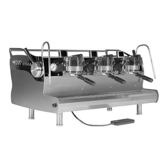
- Page 1 MVP & MVP HYDRA OWNERS MANUAL VERSION 2015.1 Last update: Oct 14, 2015 3 Group MVP *Shown with OPTIONAL Red Powder Coat Accents 5610 4th Ave S. / Sea le, WA 98108—USA Tel: +1 206 764 0600 / Fax: +1 206 764 0601 Ordering Parts: parts@synesso.com Informa on: info@synesso.com www.synesso.com...
-
Page 2: Table Of Contents
Installa on / installa on Diagram 8 ‐9 Side Panel Removal 10 Plumbing Requirements 11 Electrical Requirements 12 MVP Hydra Package & Installa on 13 Start up Instruc ons 14 MVP Hydra Bypass Setup 15 MVP & MVP Hydra, Last Show Brewed 15 Opera on 16‐18 ... -
Page 3: Introduc On
INTRODUCTION Congratula ons on the purchase of your Synesso™ espresso machine. Please read this Owner’s Manual and retain it in a safe loca on for future reference. If you have any ques ons about your machine, please con‐ tact Synesso™ and our knowledgeable staff will assist you Please WRITE your Serial Number & Offset Infor‐ Factory Contract Informa on: ma on here. This can be found on the 2nd & 3rd Synesso™ Inc. Menu Levels of the Display Controller. Have this available BEFORE calling for service or technical 5610 4th Ave South support. Sea le, WA 98108 ‐ USA Tel: +1.206.764.0600 / Fax: +1.206.764.0601 S/N: ________________________________ The offsets for this machine are: E‐mail: info@synesso.com BG1: _____°F / BG2:_____°F / BG3:_____°F Web: www.synesso.com Steam Tank:_____°F Twi er: @SynessoFactory Instagram: Synesso_factory Included in the package with this machine you will find the following: Thumb Drive containing the Owner’s Manual, MVP Series Video and other technical documents Pump/Motor Combina on + hoses (3/8” compression fi ngs on all hoses) ... -
Page 4: Safety Warnings
SAFETY WARNINGS IMPORTANT Informa on for Synesso™ Espresso Machines: DISCONNECT FROM POWER BEFORE SERVICING. Read the en re manual before opera ng this machine. Steam and condensa on from the steam wand discharge are very hot and may cause burns. The steam wand ps and bases become hot during use: do not touch these surfaces. Cover the steam wand p or submerge in a filled pitcher to safely divert the steam before opening the steam valve. Never remove the steam wand from the product that is being heated when the valve is open. Never remove the portafilter from the machine during the ac ve brewing process. Keep water and moisture away from any electrical device or live power. Steam tank water is heated to 260°F (126°C) or more; Use cau on near steam tank. The brew groups deliver water as hot as 210°F (99°C). Avoid exposure to this water. ... -
Page 5: Depressurizing Tanks, Tank Safety
BREW & STEAM TANK SAFETY Safety Precau ons: Espresso machines have numerous poten al hazards, and it is of paramount importance to Synesso™ that people servicing our machines take all necessary precau ons to ensure their personal safety. When work‐ ing on the machine’s boilers (unless otherwise instructed in the direc ons): Turn the machine off and shut off the incoming water supply. Depressurize the boilers as shown below. When working on any electrical wiring (unless checking voltage or amperage readings or otherwise in‐ structed in the direc ons) ensure that the machine is switched off at the electrical box and the machine is unplugged. Depressurizing the Steam Tank: 3. The steam tank is depres‐ 2. Open the steam valve by moving 1. Turn off the element circuit surized when the steam gauge the steam actuator lever forward breaker located under the machine reads zero. Note: the steam gauge is rated @ 0‐60 psi Depressurizing the Brew Tanks: 3. In the second level menu, 1. Turn off the element circuit 4. The brew tanks are depressur‐ breaker located under the machine. change the brew valves from ... -
Page 6: Start Up Screen, Serial #, So Ware Ver
START UP SCREEN When cycling the power on, this screen is shown momen‐ tarily . It displays your so ware version and your serial number. Understanding the informa on displayed in the serial number. i.e.: 301142030 3 ‐ is the number of groups on this machine (this is a 3 group machine) 01 ‐ is the month is was built (Jan is 01) 14‐ is the year is was built (14 is the year 2014) & 2030 is the machine sequence number RECOMMENDED TOOLS & SUPPLIES Tools and recommended items required to fully diagnose, service and maintain Synesso espresso machines. Mul Meter – reads volts, amps and ohms Small Files – Round and Triangular (The Fluke T5‐600 is recommended) Picks – Straight and Curved, an Ice Pick is great for Heat Shrink Gun or Torch replacing portafilter gaskets Vacuum with a Hose ... -
Page 7: Warranty & Water Standards
In Synesso’s experience, Everpure Claris and Cirqua formulator systems can produce a re‐ sult that can damage the Synesso stainless steel tanks. Use of either system is highly dis‐ couraged and will void the water related parts of the machine warranty. - Page 8 WARRANTY & WATER STANDARDS Synesso’s liability is limited to the purchase price of the product and shall not be held liable for damages that extend beyond the product itself. Synesso’s liability of consequen al, incidental damages, indirect or direct damages for personal injury, inability to properly use this product, loss of business profits or interrup on to business is expressly disclaimed. ** Regarding equipment sold or residing outside the United States: purchaser maybe required to pay for the shipping and associated costs for warranty parts, repairs and services. Please contact your local distributor to resolve the issue regionally, if possible. INSTALLATION To maintain the 1 year warranty, an authorized or cer fied espresso service representa ve must perform the installa on of this espresso machine. Site Prepara on ‐ See Diagram p.9 ...
- Page 9 INSTALLATION 9 ...
-
Page 10: Side Panel Removal
MVP & MVP Hydra ‐ 2 Piece Side Panels This side panel is shown with the trim plates removed, to display the way the lower panel interlocks with the upper panel. When removing the Lower Side Panel from the espresso machine: Loosen the 2 side panel moun ng bolts , but do not remove. Remove the Thumb Screw from the drain tray Push the panel to the back of the machine while li ing slightly up This allows the user easy access to the drain box & allows the technician easy access to all water control valves on the water inlet (right) side and to the level probes and thermal switches on the le side. For the technician to access the steam valve, the Upper Panel must be removed. When removing the Upper Panel from the espresso machine: Remove the 2 side panel moun ng bolts completely. Each bolt is threaded into a plate fastener inside the frame. Be careful not to lose the fasteners. The Safari Rack is suspended by, but not threaded onto, short bolts on each side panel. *The Safari Rack needs to be supported while removing the Upper Panel. -
Page 11: Plumbing Requirements
This equipment must be installed to comply with the applicable federal, state or local plumbing codes. WATER TREATMENT IS REQUIRED TO PRESERVE THE FULL MACHINE WARRANTY. Please ensure that the incoming water complies with the warranty requirements listed on page 7. Using the provided stainless steel braided hose, connect the pump to the shutoff valve on the filtered cold water line. Fi ngs on the hoses and pumps are 3/8” tube compression. Thread sealant or Teflon tape is not necessary. Make connec ons snug, but do not over ghten. Turn incoming water ON and check for leaks. Synesso™machines require a minimum of 50 PSI (3.5 bar) of line pressure at 30gal (120L) per hour to have the auto‐fill system, for the steam tank func oning properly. Please ensure that the incoming water meets this requirement or contact Synesso™for alterna ve methods of boos ng water pressure. NOTE: Synesso™sells a “Euro‐hose” adaptor hose and fi ng (part number is 1.5020) which converts from a 3/8” tube fi ng to a pipe fi ng, suitable for most non‐US plumbing. Please refer to the picture below to iden fy the differences between the standard and Euro‐style fi ngs and hoses. 3/8” BSP Pipe Euro Hose ‐ #1.5010 Euro Fi ng ‐ #1.5000 1/4” NPT (Euro Assembly ‐ #1.5020) ... -
Page 12: Electrical Requirements
SPECIAL ELECTRICAL INFORMATION FOR EMC‐COMPLIANT MACHINES (C‐TICK FOR AUSTRALIA, CE FOR EUROPE AND OTHER LOCATIONS) To comply with EMC (Electromagne c Compa bility) regula ons, Synesso™is required to install a capacitor in the electronics box across the main power IN. To avoid an electric shock from the charge held in the ca‐ pacitor, unplug the cord, taking care to NOT touch the metal prongs on the plug end. Turn the electronics ON/OFF red rocker switch to the ON posi on and wait a few seconds un l the red switch “goes dark.”... -
Page 13: Mvp Hydra Package & Installa On
MVP HYDRA PACKAGE REQUIREMENTS & INSTALLATION MVP Hydra Installa on Requirements: Electrical: The Hydra package has a slightly greater amp draw than the single pump machines; please note the max amp draws and plan your electrical installa on accordingly. See table on page 12. Each pump motor has a dis nct color associa on, which is indicated throughout the machine by colored wires and zip es. The colors are as follows: Group 1: Grey Group 2: Purple Group 3: Brown Water inlet for the steam tank: Pink Wherever these colors are seen, it is cri cal for proper machine func on that they are matched up correct‐ ly (grey to grey, etc.) for both electrical and plumbing systems. Plumbing: Hydra packages require one incoming water source like single pump machines. The water passes through a manifold (commonly part of the line pressure regulator) and is distributed to each pump. Once again, fol‐ low the color coding for proper installa on of the hoses from the output of each pump to the machine. ... -
Page 14: Start-Up Instruc Ons
4. Bleed the group heads of air: Hold each brew group handle le un l the corresponding display reads M: shi each group head handle le momentarily, (see pictures below) allow the group to run un l there is a steady flow of water. Shi each group head right to turn off. 5. Wait un l the steam tank has stopped filling and the level in the sight glass reads at least ½ full. Turn the hea ng element breaker to the ON or (1) posi on. All the hea ng elements (brew and steam) are now ac ‐ vated. 6. To adjust the pump pressure, ac vate the pump by shi ing the brew group handle momentarily le two mes on MVP and three mes on MVP Hydra. 7. Locate and read the pump pressure / brew gauge located to the right of the rightmost group on MVPs and to the right of each group on MVP Hydras. 8. Set the pump pressure to 9 Bar: ... -
Page 15: Mvp Hydra Bypass Setup
With these se ngs in place, you can taste the effects of pressure ramping applied to each shot. The shot be‐ gins with pre‐infusion. Low pressure water saturates the puck, swelling it to reduce channeling. A er the pre ‐infuse me has elapsed, ramp up (bypass) begins. The bypass system creates a slow rise in water pressure by par ally diver ng water away from the brew group. A er the ramp up me ends, the bypass closes and a brew pressure (9 bar) stage begins. Ramp down returns to bypass pressure. When in M or MP mode, the op‐ erator enters ramp down by moving the group top actuator momentarily to the le . Volumetric groups can be programmed to automa cally begin ramp down at a set percentage of the shot as described on page 20. MVP & MVP HYDRA INTRODUCTION The MVP Hydra is a machine model with a pump and motor for each group head. The MVP Hydra has inter‐ nal plumbing and wiring to accommodate separate and dis nct pressures in each brew group. In contrast, an MVP has a single pump and motor for the en re machine. Having individual pumps and motors allows the operator to control brewing pressure at each group head, and each brew group func ons independently without affec ng the pressure at the other groups. MVP Hydra groups can func on in Manual mode (M) with full manual control, in Manual Program mode (MP) with med pre‐infusion and pressure ramp up, or in Volumetric Program mode (VP) with programmed pressure ramping. Any group head can be changed on the fly to any configura on at any me. Last Shot Brewed: The MVP and MVP Hydra have a storage feature where the last brewing func on is stored in a temporary memory. This applies to any brewing func on. If you quickly purge a screen, this will be stored as the last shot brewed. If you manually brew an espresso that is perfect, this is the last shot brewed. The following ... -
Page 16: Opera On
Hold handle LEFT to change the Opera on Mode from M (Manual) to MP (Manual Program) to VP (Volumetric Program). M ‐ Manual 5. Pre‐infuse the coffee puck by momentarily shi ing the brew group le . This allows line pressure to satu‐ rate the puck. 6. When a drip shows at the spout (or on the basket if bo omless,) momentarily shi the brew group le again to advance the process. Repeat to con nue advancing thru the brewing process un l complete. 7. You can end the shot by momentarily shi ing the group cap right at any me while brewing. If brewing in manual program mode con nue to step 8 (Manual Program) MP ‐ Manual Program 8. Manual Program allows a me to be set for pre‐infusion (and also for ramp up on MVP Hydra models.) At the comple on of the set me the next stage begins automa cally. If “0” is selected for the amount of me then the stage will be skipped. 9. When the process has advanced to full pressure brew (9 bar) the operator shi s to the next brew stage 16 ... - Page 17 VP ‐ Volumetric Program 5. Select a program to run by momentarily shi ing the corresponding group head right, this will shi through the programs displayed on the shot mer. There are six to choose from. Some may be turned off, and there‐ fore not displayed. 6. Check the program on the hand held controller. Press the down arrow to move to the corresponding group. The program number and pressure mes are displayed on the first screen, and the percentage of shot brewed and total water count on the next screen. See pages 20 ‐ 21. 7. The shot will automa cally end once the set total water count has been registered. Brew Pressure Graph Pre‐infuse Bar Ramp Up Bar Brew Pressure Bar Ramp Down Bar Display Func ons 5 Minute Time Out Er‐ Shi LEFT to SAVE to Steam Tank, Low Water SAVE Lockout is ON ror or Low Flow Error Program 5 Level or Low Flow Error 6 Programs Shown. Only the selected MVP Brew Pressure Graph. program displays when in use. 17 ...
- Page 18 6. As the milk agitates and heats, lower the pitcher to keep the p of the steam wand closer to the surface. Allow the steam jets to push some air beneath the surface, then raise the pitcher to lower the p of the wand deeper into the milk. This will con nue the hea ng process and minimize further foaming. Do not touch the steam wand to the bo om of the milk pitcher; this can create an inaccurate temperature meas‐ urement. 7. Heat milk to approximately 150F to 170F (65°C to 76°C). If you are using your hand to help determine the temperature, it will feel about as hot as you can stand without burning yourself. Milk thermometers are also an excellent way to determine the temperature of the milk. Cau on: Do not overheat the milk and scald it. Scalded milk should not be used. 8. Remove the wand from the milk, purge with steam, and wipe clean immediately a er each use. NOTE: Although Synesso™steam wands are made with a proprietary double‐walled process that helps to keep the outer wall cooler, the p and base can become very hot and cau on must be used. NOTE: Whole Milk, 2%, 1%, Non‐Fat, Soy Milk, Rice Milk and other milk type products may require different techniques to foam properly. In general, the higher the fat content, the easier it is to steam. 18 ...
-
Page 19: Programming - Handheld Controller
PROGRAMMING This programming sec on applies to all MVP Synesso™ machines. MVP machines have a hand held (wired) controller, pictured below, to allow the user to comfortably view and change the machine se ngs. To change se ngs on these screens, first press the line bu on on the le side of the display associated with the se ng you wish to change. The value will flash once selected. Press the up or down bu ons un l the desired value is displayed. -
Page 20: Factory Se Ngs
Total Water Count 380 Menu Level 1: Group 1, Program 1 Line 1 of the first brew group control screen indicates the current temperature of the brew tank as measured by its probe. Once this temperature reaches the set point, it will con nuously cycle up and down by small increments as the electronics balance the temperature. This line also indicates the ac ve program (PRG1 in this case). Changing the ac ve program will update the se ngs on lines below. Line 2 is indica ng the set point of 202.0F (94.4C). Line 3 indicates the length of me pre‐infusion is set for in the current program. When star ng a shot in MP or VP mode, pre‐infusion will allow line pressure water to soak the puck for as long as indicated before mov‐ ing on to the next brew phase. Se ng the pre‐infusion me down to 0.0 seconds will skip the pre‐infusion phase in MP and VP modes. One step lower than 0.0 is the “MAN” se ng, which will require the operator to exit the pre‐infusion phase manually in MP mode, and will skip pre‐infusion in VP mode. Line 4 indicates the length me set for the ramp‐up phase in the current program. This op on will ONLY be visible on MVP Hydra models. Ramp‐up me begins once the pre‐infusion stage has finished. To cycle to the next display screen, press the down bu on. 20 ... -
Page 21: Steam Temperature Control
PROGRAMMING Line 1 indicates the brew group and program associated with the se ngs below. Line 2 shows the percent of the total water count at which the machine will ramp the shot pressure down. Lowered pressure near the end of the shot will change the extrac on rate and alter the flavor of the shot. Line 3 and 4 show the total water count associated with the current program. As indicated, there are about 4.5 ‘counts’ per milliliter dispensed by the machine. Some of this dispensed water is absorbed and retained by the coffee puck, but generally, if you add 9 counts, you should receive 2 addi onal mL of water. To cycle to the next display screen, press the down bu on. Menu Level 1: Steam Tank Line 1 shows the current reading of the steam tank temperature probe (250.7F in this example). Once this temperature reaches the set point, the digital display will con nuously cycle up and down by small incre‐ ments as the electronics balance the temperature. Line 2 is indica ng the set point of 250.0F (121.1C). The adjustable set range for the steam tank is between 200F and 265F (93.3C and 129.4C). Line 3 and 4 are indica ng that the independent loops 1 and 2 of the hea ng element are ac ve. NOTE: Turning off either loop 1 or 2 of the element can be used as a troubleshoo ng procedure and is not a recommended method of energy conserva on. To cycle to the next display screen, press the down bu on. 21 ... -
Page 22: Hot Water Tap
PROGRAMMING Menu Level 1: Hot Water Tap Line 1 indicates that you are on the hot water tap control screen. Line 2 indicates the adjustable amount of me that the hot water tap will run before shu ng off. Line 3 gives the op on of se ng the hot water me on line 2 by ac va ng the tap and le ng the water flow, then shu ng it off. The machine will store the dura on of this pour as the new dispense me. To cycle to the next display screen, press the down bu on. Menu Level 1: Auto Backflush Auto backflush can be ac vated by pressing the line bu on associated with the group you want to flush. Set the value to “ready”, then place a portafilter equipped with a blind basket into the selected brew group. Shi le on the group head. The selected group will run the brew valve and motor for 10 seconds, followed by 10 seconds off. This will repeat 5 mes. The shot mer will count up to 10 to let you know when it is running. Upon comple on, the ... -
Page 23: Brew Error Codes
PROGRAMMING Menu Level 1: Brew System Error Codes In an effort to prevent damage to machines and to help operators troubleshoot issues, Synesso™ has engi‐ neered several safeguards into the programming. By understanding these codes, operators can remedy is‐ sues more quickly. The most recent error can be found on the temperature overview screen at the lower right corner. BR ‐ Brew System GROUP GROUP GROUP Codes 1 2 3 CODE DESCRIPTION BV ‐ Brew valve BRBV01 BRBV02 BRBV03 Brew Valve has been on for 5 consecu ve minutes ... -
Page 24: Menu Level 2 - Se Ngs
PROGRAMMING There are 3 levels of menus a technician can access through the wired controller: Menu level 1 described on pages 19‐23 contain se ngs relevant to the day‐to‐day opera on of the machine. Menu level 2 may be reached from level 1 and contains se ngs relevant to technicians and machine owners. To access menu level 2, first press the home bu on to return to the temperature overview screen. Next, press and hold the home bu on. Press and release the 4th line bu on, then release the home bu on. Menu Level 2: Lockout This is the first screen of the 2nd level of menus, the right hold save lockout screen. ... -
Page 25: Temperature, Fahrenheit & Celsius
PROGRAMMING Menu Level 2: Temperature (F or C) This is the temperature display screen. Line 2 indicates the Temperature scale that you are currently in (Fahrenheit or Celsius). Line 4 indicates the opera on status of the machine’s brew valves. Se ng the brew valve func on to [ON] will ac vate the brew valves, allowing the pressure to be bled from the brew tanks. Once the pressure has dropped, turn the brew valve se ng back to [NORMAL] and a ach the appropriate drain hose to the brew group’s drain tube. Turn the brew valve se ng back [ON] once the drain hoses are securely a ached. This will allow the water in the brew groups to fully drain in approximately 5 minutes. When the brew groups are finished draining, set the Brew Valve indicator back to the [NORMAL] se ng. If the draining process takes longer than 5 minutes, the machine’s safety programming will automa ‐ cally turn the brew Valve indicator to the [NORMAL] se ng while exi ng back to the temperature overview screen. If more me is needed, return to the Temperature Display screen and set the Brew Valve display back to the [ON] posi on to finish the procedure. Once finished with the draining procedures, make sure the Brew Valve indicator is set back to the [NORMAL] posi on. To cycle to the next display screen, press the down bu on. Menu Level 2: Line Pressure Boost 25 ... -
Page 26: Brew Offsets
Menu Level 2: Line Pressure Boost If the machine has an op onal line pressure boost pump installed, you will see this menu screen, otherwise it will not be shown. “AUTO” is the se ng on line 2 for normal opera on. In “AUTO” mode, whenever a brew valve or water con‐ trol valve is ac vated, the power board will also trigger a pump relay to run a line pressure genera ng pump and motor package. If this is set to “OFF”, the line boost motor will not ac vate. The “ON” se ng will run the boost motor constantly. This is factory set to “OFF” to protect the boost pump from running without water. To cycle to the next display screen, press the down arrow Menu Level 2: Brew Offset Line 2 indicates the measured water temperature at the selected brew group’s temperature probe. Line 3 indicates the temperature adjustment made at the Synesso™ factory, in order to match the measured temperature with the temperature desired inside the puck. The Synesso™ tes ng method is as follows: Using a bo omless portafilter, dose out 16‐18 grams of coffee into a 14 gram basket with a thermal probe inserted 1/8th of an inch from the surface and in the middle of the puck, packing and tamping the grounds in the basket as usual. The thermal probe is then wired to a FLUKE thermometer to relay the actual temperature of the water flow‐ ing through the puck while pouring a 25 second, 2 ounce shot. This process is repeated a minimum of 3 mes per brew group in order to get the most accurate readings. The difference between the measured puck tem‐ perature and the raw tank temperature becomes the brew offset This offset should not be altered without thoroughly tes ng the puck temperature, as men oned above. To cycle to the next display screen, press the down bu on. 26 ... -
Page 27: Steam Offset
PROGRAMMING Menu Level 2: Steam Offset Line 2 indicates the measured steam temperature at the steam tank temperature probe. Line 3 is the offset used to calibrate the steam tank temperature and pressure so that when the steam tank is set at 250f, there is 1.3bar pressure on the gauge. Line 4 of this display screen is showing a 5 second delay. The fill probe will wait this long before turning the steam tank fill valve on or off. Add me here if the machine is in an unstable installa on such as a food truck or catering cart. There is no need to drop this me below 5 seconds. To cycle to the next display screen, press the down bu on. Menu Level 2: System Clock This is the system clock screen. Line 2 allows the operator to set the local me in a 24 hour format. Line 3 and 4 allow the operator to set the current date. The date and me are used for both the error log and the power saving mode. A small ba ery on the power board should keep the clock and calendar running if the machine loses power, but it will need to be re‐ placed eventually. Refer to the markings on the ba ery for replacement info. To cycle to the next display screen, press the down bu on. 27 ... -
Page 28: Power Save Mode
PROGRAMMING Menu Level 2: Power Save Mode ‐ Enabled Line 2 of the Power Save Mode in this example is indica ng the mers are [ENABLED], making adjustments to lines 3 and 4 available. If line 2 reads [DISABLED], no further se ngs will be available on this screen. Menu Level 2: Power Save Mode ‐ Disabled Line 3 indicates the se able me at which your power save mode will start, cooling the machine to lower heat levels overnight. Line 4 indicates the se able me at which your power save mode will end, hea ng the machine back up to the set points. ... -
Page 29: Error Log
PROGRAMMING Menu Level 2: Error Log Line 1 of the error log screen shows how many errors the machine has recorded, up to the 35 most recent errors, and which of these you are currently viewing. This example is showing the second of two errors. Line 2 indicates the error code. If the error log is clear, this line will simply read ‘NO ERRORS’ as shown be‐ low. Line 3 indicates the date and me that the last error has occurred. If no error has occurred, this line will be blank. Line 4 gives the op on to scroll through or clear the error log. To view older errors, press the 4th line bu on once, which will make [SCROLL] flash. Use the up and down bu ons to change the viewed error. Press the 4th line bu on again and [CLEAR] will begin flashing instead of [SCROLL]. Press the 4th line bu on again to deselect both op ons. 29 ... -
Page 30: Return To Opera Ons (Level 1 Menu)
Menu Level 2: Error Log To clear the Error Log, press the 4th line bu on 2 mes so that [CLEAR] is flashing. Press an arrow bu on to select clear. The 4th line will ask you to confirm clearing the error log as shown below. Change the flashing [NO] to [YES] to immediately clear the log. Press the 4th line bu on with [NO] s ll flash‐ ing to exit without clearing the log. See page 23 for descrip ons of the error codes you may see. To cycle to the next display screen, press the down bu on. Menu Level 2: Return to Opera ons This is the last screen in the second level of menus. Pressing the 3rd line bu on will take you back to the temperature overview screen in the 1st level of men‐ us. Access to the 3rd level of menus is only available from this screen. Menu level 3 contains machine configura on se ngs which do not change over the life of the machine. ... -
Page 31: Maintenance
MAINTENANCE DAILY MAINTENANCE Proper and regularly scheduled cleaning and maintenance procedures are CRITICAL for trouble‐free and op ‐ mum quality performance from your espresso machine. Backflushing This process forces water through the inlet tube and drain system. This should be performed on EACH brew group daily. To Backflush: 1. Replace the filter basket with the ‘blind’ basket, which has no filter holes. 2. Engage the portafilter, then follow the instruc ons on page 22 to use the auto backflush func on. 3. When using an approved espresso industry detergent during backflushing, follow the manufacturer’s in‐ struc ons. It is extremely important to thoroughly rinse the blind filter basket and repeat backflushing sever‐ al mes with clean water to clear the system of any detergent residue. Failure to rinse can cause valve prob‐ lems and bad flavor. NOTE: NEVER remove the screen and screw when backflushing. Remove and clean them a er backflushing is complete. Do not forget to reinstall. General machine cleaning 1. Clean the surface of the machine using a so damp cloth. Avoid using abrasive cleaners or cleansing pads. Take extra care on the mirror finish stainless steel surfaces. A “micro‐fiber” towel is recommended to avoid scratches. 2. Make sure the steam wands and ps are free of milk build‐up. It is always best to clean the steam wand and p a er each use. Approved espresso industry cleaners can be used to dissolve milk build‐up. Tips can be removed to soak. 3. The drip tray, drip tray grates, and portafilters should be removed and cleaned every day. If you clean the portafilters in the dishwasher, first remove the filter baskets and springs before washing. 31 ... - Page 32 3. Wipe down the en re machine with a so cloth. 4.Remove portafilters, baskets and springs, drip tray and grates and clean thoroughly. These items are all dishwasher safe. 5. Slowly pour a pitcher of hot water down the drain to clear grounds debris and prevent blockage. Weekly 1. Soak portafilters and the removed filter baskets in an approved espresso industry detergent and water solu on overnight. Rinse thoroughly before reassembling and using your p ortafilters. 2. Carefully remove screens from each brew group using a short handled screwdriver and soak overnight in a similar solu on as the portafilters. 3. Rinse screens thoroughly before installing and using. Make sure you install the screens before brewing any shots of espresso. Failure to do so may plug the drain lines with coffee grounds. Monthly 1. Check your water filtra on system and make sure the cartridges and filters are changed as needed. In ar‐ eas of high mineral content, hard water, high par culate count or in very busy loca ons, the filtra on sys‐ tems will need to be checked more o en. Quarterly 1. Change portafilter gaskets and closely inspect diffuser screens and filter baskets, If these items are show‐ ing wear, please replace them as soon as possible. Change these items if they show damage or overuse. 2. Briefly inspect the machine for leaks or poten al issues. Contact Synesso™or your local distributor or ser‐ vice agent to order parts and/or request service. Synesso™recommends that you contact your distributor or service agent for periodic maintenance. The fre‐ quency of maintenance visits will depend on a variety of factors including how much use the machine re‐ ceives, but at least one preventa ve maintenance visit a year is required. During this yearly service, all body panels must be removed and all connec ons both electrical and hydraulic must be inspected. Small prob‐ lems can become large if not caught early. 32 ...
-
Page 33: Trouble Shoo Ng Guide
Tamp pressure is too light Not enough coffee in the basket Grind is too coarse Portafilter baskets are worn or cracked; replace Brew temperature is too cold Crema is thin with large bubbles and tastes astringent: Coffee is old Grinder burrs are dull Brew temperature may be set too low Diffuser screen is loose: This is most likely caused by over filling the portafilter basket with coffee. This causes the expanding coffee puck to push against the diffuser and bend the screen‐to‐screw contact point away from the screw. No pump pressure when water flows from the group: Check which brew stage the group is in (shot mer pressure graph shows three bars for pump pressure.) In M mode, it takes several shi s le to reach full pump pressure (2 for MVP, 3 for MVP Hydra.) In MP or VP mode, pre infusion and/or ramp up me may be set to run too long. Pump relay may have failed The pump comes on, gauge reads full pressure, but no water comes out: 33 ... -
Page 34: Troubleshooting
TROUBLESHOOTING Diffuser screen/screw, or jet is clogged Soap residue not fully flushed a er cleaning has glued the valve closed (tap the valve body gently). Brew solenoid has been sealed shut by dried soap or has failed. Brew Gauge Brew Pressure gauge needle value changes o en: This is normal. The lowest number (usually 3‐5 bar) reflects the incoming line pressure. When brewing the needle reflects brew pressure (8.5‐9 bar). When the brew tanks heat, the water expands and the ex‐ pansion valve relieves the pressure at 11 or 12 Bar. Brew Pressure is Low: Check pump to make sure pressure is properly set Water supply hose to the pump is kinked Water filter is plugged. Check and replace if necessary Pump Motor Runs; No Brew Pressure: Failed pump, needs to be replaced Brew Solenoid is stuck (can be caused by soap residue not fully flushed a er cleaning). Brew Solenoid has failed The line between the pump and the water supply has collapsed or is kinked Hose to the pump is kinked Water filter is plugged. Check and replace if necessary Water supply is inadequate ... -
Page 35: Steam Wand
TROUBLESHOOTING Steam Wand Drip at the Steam Wand Tip: Steam valve seal is worn. Replace by installing steam valve rebuilt kit. Steam valve is filled with milk residue. Disassemble steam valve and clean. Wand is Hard to Move or S cky: Remove wand at the nut, clean and lubricate moving parts with food grade grease Steam Sudden loss of steam pressure: Commonly caused from drawing large amounts of hot water while steaming milk. Allow the machine me to recover pressure. Check temperature se ngs on Steam 1 and 2 to make sure they are high enough for your applica on. Watch the steam gauge when the pressure drops; allow the hea ng ele‐ ments to heat the incoming cold water. When it reads above 1.1 bar, hot water and steam may be dis‐ pensed again. Check the wired controller to make sure all temperatures, especially in the steam tank, are close to their set points. Check the element breaker on the electronics box to make sure the hea ng elements are ON (element switch is to the le ). Steam Tank is overfilling: Water is too so ; this occasionally happens with reverse osmosis water filtra on systems. The water lev‐ el (auto fill) probe needs a minimum mineral content in order to detect water. ...
Need help?
Do you have a question about the MVP and is the answer not in the manual?
Questions and answers