
Related Manuals for Bosch Rexroth SB24/34


Summary of Contents for Bosch Rexroth SB24/34
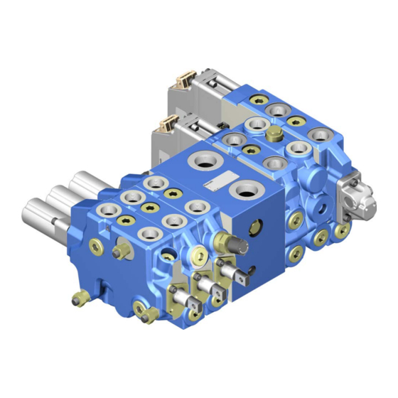
- Page 1 Load-sensing control block SB24/34 for mobile applications Instruction manual RE 66170-B/2019-05-15 English...
- Page 2 © Bosch Rexroth AG 2019. All rights reserved, also regarding any disposal, exploitation, reproduction, editing, distribution, as well as in the event of applications for industrial property rights. The data specified within only serves to describe the product. No statements concerning a certain condition or suitability for a certain application can be derived from our information. The information given does not release the user from the obligation of own judgment and verification.
-
Page 3: Table Of Contents
5.3.19 Intermediate plate Control block versions 5.4.1 Examples for control blocks with connecting plate, end plate and central connecting plate 5.4.2 Examples for control blocks with connecting plate or end valve Combination options RE 66170-B/2019-05-15, Control block SB24/34, Bosch Rexroth AG... - Page 4 11.3 Removal of control block/control block segment from machine 11.4 Preparing the components for storage or further use Disposal Extension and conversion Troubleshooting 14.1 How to proceed for troubleshooting 14.2 Malfunction table Technical data Alphabetical index Bosch Rexroth AG, Control block SB24/34, RE 66170-B/2019-05-15...
-
Page 5: About This Documentation
Contains all information required for directional valve installation Order confirmation Order confirmation Contains the order-related technical data of the control block. Offer drawing Offer drawing Contains the outer dimensions, all connections and the hydraulic circuit diagram of the control block. RE 66170-B/2019-05-15, Control block SB24/34, Bosch Rexroth AG... -
Page 6: Representation Of Information
• Type and source of danger: indicates the type and source of the danger • Consequences: describes what occurs if safety instructions are disregarded • Precautions: states how the danger can be avoided Bosch Rexroth AG, Control block SB24/34, RE 66170-B/2019-05-15... -
Page 7: Symbols
EHR24-EM2 Control valve with PWM signal-controlled electrohydraulic hitch control Control valve Directional valve type SB Control valve Directional valve type EHR Control spool Main spool actuation Type of control spool actuation RE 66170-B/2019-05-15, Control block SB24/34, Bosch Rexroth AG... -
Page 8: Abbreviations
End valve (with LS signaling direction from right to left) End plate Individual pressure compensator International Organization for Standardization Pulse width modulation Non-return valve Single-acting Check valve Central connecting plate Intermediate plate Bosch Rexroth AG, Control block SB24/34, RE 66170-B/2019-05-15... -
Page 9: Safety Instructions
Information about approved hydraulic fluids can be found in the corresponding data sheet. Intended use includes having completely read and understood this documentation and particularly chapter 2 "Safety instructions" on page 9. RE 66170-B/2019-05-15, Control block SB24/34, Bosch Rexroth AG... -
Page 10: Improper Use
2.3 Improper use Any use other than that described as intended use is considered improper. Bosch Rexroth AG is not liable for damages resulting from improper use. The user is solely responsible for any risks arising from improper use. The following foreseeable forms of faulty usage are also considered improper (this list is not exhaustive):... -
Page 11: Product-Specific Safety Instructions
▶ Use suitable lifting gear for transport. ▶ Observe the prescribed position of the lifting strap. ▶ Observe the national laws and specifications of occupational safety and health and transport. RE 66170-B/2019-05-15, Control block SB24/34, Bosch Rexroth AG... - Page 12 ▶ Depressurize the relevant machine/system component and repair the leak. ▶ Never attempt to block or seal the leak or hydraulic fluid jet with a cloth. Bosch Rexroth AG, Control block SB24/34, RE 66170-B/2019-05-15...
-
Page 13: Personal Protective Equipment
The personal protective equipment is the responsibility of the user of the control block/control block segment. Observe the safety regulations in your country. All pieces of personal protective equipment should be intact. RE 66170-B/2019-05-15, Control block SB24/34, Bosch Rexroth AG... -
Page 14: General Instructions On Property Damage And Product Damage
Ingress of fluids and foreign bodies due to lacking sealings and locks! Loss of the protection class and danger of short circuit! ▶ Before the assembly, ensure that all sealings and locks of the plug-in connection are tight. Bosch Rexroth AG, Control block SB24/34, RE 66170-B/2019-05-15... - Page 15 Dispose of the control block/control block segment, hydraulic fluid, and packaging in accordance with the national regulations in your country. ▶ Dispose of the hydraulic fluid in accordance with the applicable safety data sheet of the hydraulic fluid. RE 66170-B/2019-05-15, Control block SB24/34, Bosch Rexroth AG...
- Page 16 • Removal of the tamper-proof caps and seals (e.g. with pressure settings), • Control of the settings at the factory, • Unauthorized conversions and additional installations, • Opening of the directional valve, • Improper handling, • Use of non-original spare parts by Rexroth. Bosch Rexroth AG, Control block SB24/34, RE 66170-B/2019-05-15...
-
Page 17: Scope Of Delivery
Included in the scope of delivery: • Control block or control block segment according to order confirmation The following parts are also assembled prior to delivery according to version: • Protective covers • Protective plugs/threaded plugs RE 66170-B/2019-05-15, Control block SB24/34, Bosch Rexroth AG... -
Page 18: About These Products
3 Designation of origin 5 Data Matrix code 6 Range/serial number The information on the above name plate may vary depending on order-specific requirements. Any other labeling on the product is just for Bosch Rexroth-internal purposes. Bosch Rexroth AG, Control block SB24/34, RE 66170-B/2019-05-15... -
Page 19: Product Description
The SB24/34 control block segments illustrated below are described by means of dummies. For a precise overview of all available combinations, refer to the respective data sheet. For the precise position and designation of external ports, refer to the data sheet or the offer drawing. RE 66170-B/2019-05-15, Control block SB24/34, Bosch Rexroth AG... -
Page 20: Types Of Actuation
Flange surface O-ring opposite side or connecting plate outer side Side Lower side Side Front face side A (EHS side) Side Front face side B Side Flange surface O-ring side or end plate outer side Bosch Rexroth AG, Control block SB24/34, RE 66170-B/2019-05-15... -
Page 21: Port Designation
Block return flow Secondary pressure relief valve return optional flow (consumer port B) (depressurized) LS signal Clean oil return flow optional EHS pilot oil return flow optional EHS pilot oil supply optional Tie rod RE 66170-B/2019-05-15, Control block SB24/34, Bosch Rexroth AG... -
Page 22: Connecting Plate For Fixed Pump (C2)
P line by means of the pressure compensator. Primary pressure relief valve : Limits the pressure at the inlet port and indirectly also the pressure in the block-internal P line. Bosch Rexroth AG, Control block SB24/34, RE 66170-B/2019-05-15... -
Page 23: Connecting Plate For Fixed Pump (C4)
Tie rod bore with thread Tie rod bore, continuous optional Block mounting thread Table 10: Internal functions Position Designation Information Pressure compensator LS pressure relief valve optional Primary pressure relief valve optional RE 66170-B/2019-05-15, Control block SB24/34, Bosch Rexroth AG... - Page 24 NOTICE! The primary pressure relief valve with its short response time and low flow is applied for limitation of the pressure peaks in the supplied flow. Operation / control The C4 connecting plate is not equipped with manual operating elements or external control functions. Fluidplan Bosch Rexroth AG, Control block SB24/34, RE 66170-B/2019-05-15...
-
Page 25: Connecting Plate (C3)
RFB-R bridge : Relieves the RfB return line for block-internal return flow R. Operation / control The C3 connecting plate is not equipped with manual operating elements or external control functions. Fluid plan RE 66170-B/2019-05-15, Control block SB24/34, Bosch Rexroth AG... -
Page 26: Connecting Plate For Variable Pump (C6)
P line. NOTICE! The pressure relief valve with its short response time and low flow is applied for limitation of the pressure peaks in the supplied flow. Bosch Rexroth AG, Control block SB24/34, RE 66170-B/2019-05-15... - Page 27 This way, the pressure in the block-internal EHS pilot oil line X is increased to the pressure value of the pressure reduction function. If the switchable solenoid is not energized, the block-internal EHS pilot oil line X is relieved to the return flow. Fluid plan RE 66170-B/2019-05-15, Control block SB24/34, Bosch Rexroth AG...
-
Page 28: Hitch Control Valve Ehr24-Em2
Lifting control unit Lowering control unit Shuttle valve CAUTION! The treaded plugs on the valve side and threaded plug must not be removed! The threaded bores are not designed for connection fittings. Bosch Rexroth AG, Control block SB24/34, RE 66170-B/2019-05-15... - Page 29 Operation / control It is operated via proportional solenoid coil of lifting solenoid and lowering solenoid by means of PWM pilot signal. Lifting solenoid and lowering solenoid optionally with manual auxiliary actuation. Fluid plan RE 66170-B/2019-05-15, Control block SB24/34, Bosch Rexroth AG...
-
Page 30: Hitch Control Valve Ehr24-Ehs
Secondary pressure relief valve Threaded plug R internal CAUTION! The treaded plugs on the valve side and threaded plugs must not be removed! The threaded bores are not designed for connection fittings. Bosch Rexroth AG, Control block SB24/34, RE 66170-B/2019-05-15... - Page 31 : Limits the operating pressure in working port Operation / control Control is realized via CAN bus pilot signal Secondary pressure relief valve optionally with manual auxiliary actuation Fluid plan EHR24-EHS sa for external return flow RE 66170-B/2019-05-15, Control block SB24/34, Bosch Rexroth AG...
- Page 32 32/78 About these products EHR24-EHS sa with internal return flow EHR24-EHS da Bosch Rexroth AG, Control block SB24/34, RE 66170-B/2019-05-15...
-
Page 33: Control Valve Sb24-M Without Individual Pressure Compensator
Cover plate optional Bearing block optional CAUTION! The threaded plugs on the CVL valve side and EVL valve side must not be removed! The threaded bores are not designed for connection fittings. RE 66170-B/2019-05-15, Control block SB24/34, Bosch Rexroth AG... - Page 34 : Disengages the deflected control spool in detent position at a set hydraulic operating pressure from the detent position. Spring cap : Encloses the spring assembly Operation / control Control is realized mechanically via control spool deflection Fluid plan SB24-M, deflection side A Bosch Rexroth AG, Control block SB24/34, RE 66170-B/2019-05-15...
-
Page 35: Control Valve Sb24-M With Individual Pressure Compensator
Control spool deflection Working port Working port LS signal output Coupling port optional Connection valve port side End valve closing side Tie rod bore Block mounting thread optional Coupling mounting thread RE 66170-B/2019-05-15, Control block SB24/34, Bosch Rexroth AG... - Page 36 P. The integrated non-return valve function prevents the return flow to the block-internal channel P. Flow controller : Limits the valve-internal inlet flow of the block-internal channel P. Check valve : Prevents valve-internal return flow in working port Bosch Rexroth AG, Control block SB24/34, RE 66170-B/2019-05-15...
- Page 37 Operation / control Control is realized mechanically via control spool deflection Fluid plan SB24-M, deflection side A, with check valve with thermal PRV SB24-M, deflection side B, with check valve with thermal PRV RE 66170-B/2019-05-15, Control block SB24/34, Bosch Rexroth AG...
-
Page 38: Control Valve Sb24-Ehs
Table 24: Internal functions Position Designation Information Valve axis Individual pressure compensator with check valve function Electrohydraulic EHS actuating unit Check valve optional Check valve with thermal PRV optional Shuttle valve Threaded plug Bosch Rexroth AG, Control block SB24/34, RE 66170-B/2019-05-15... - Page 39 The discharged volume is very low. Shuttle valve : Directs the higher LS pressure through the control block/control block segment. Operation / control Control is realized via CAN bus pilot signal SB24-EHS Fluid plan RE 66170-B/2019-05-15, Control block SB24/34, Bosch Rexroth AG...
-
Page 40: Control Valve Sb34-Ehs
Table 26: Internal functions Position Designation Information Valve axis Individual pressure compensator Electrohydraulic EHS actuating unit Check valve Check valve with thermal PRV optional Shuttle valve Threaded plug Cover cap with manual auxiliary actuation optional Bosch Rexroth AG, Control block SB24/34, RE 66170-B/2019-05-15... - Page 41 CAUTION! During normal operation, the manual auxiliary actuation must not be locked and tools must not be applied or attached. Operation / control Control is realized via CAN bus pilot signal RE 66170-B/2019-05-15, Control block SB24/34, Bosch Rexroth AG...
-
Page 42: End Plate E1
Fluid plan SB34-EHS 5.3.16 End plate (E1) Table 27: External ports Position Designation Information Tie rod bore Table 28: Internal functions Position Designation Information Connection Y → R Fluid plan End plate E1 Bosch Rexroth AG, Control block SB24/34, RE 66170-B/2019-05-15... -
Page 43: End Plate (E2)
This way, the pressure in the block-internal EHS pilot oil line X is increased to the pressure value of the pressure reduction function. If the switchable solenoid is not energized, the block-internal EHS pilot oil line X is relieved to the return flow. RE 66170-B/2019-05-15, Control block SB24/34, Bosch Rexroth AG... -
Page 44: Central Connecting Plate
Shuttle valve optional Shuttle valve with spring pretension optional Pressure relief valve optional Pressure reducing valve optional Pressure reducing valve switchable solenoid optional Pressure reducing valve threaded plug optional Rx-R non-return valve optional Bosch Rexroth AG, Control block SB24/34, RE 66170-B/2019-05-15... - Page 45 This way, the pressure in the block-internal EHS pilot oil line X is increased to the pressure value of the pressure reduction function. If the switchable solenoid is not energized, the block-internal EHS pilot oil line X is relieved to the return flow. RE 66170-B/2019-05-15, Control block SB24/34, Bosch Rexroth AG...
-
Page 46: Intermediate Plate
Fluid plan Central connecting plate 5.3.19 Intermediate plate Table 33: External ports Position Designation Information Tie rod bore The intermediate plate does not have any internal function and serves as spacer. Fluid plan Bosch Rexroth AG, Control block SB24/34, RE 66170-B/2019-05-15... -
Page 47: Control Block Versions
Mixed control block with EHR24-EM2 Mixed control block with EHR24-EM2 and central connecting plate The inlet and return lines of the flow can be directed via the C6 connecting plate or the central connecting plate. RE 66170-B/2019-05-15, Control block SB24/34, Bosch Rexroth AG... -
Page 48: Examples For Control Blocks With Connecting Plate Or End Valve
Mixed control block with SB24-M, EHR-EM2, ZAP, EHR-EM2 and SB24-M EVL SB24-M EVL and SB34-EHS CVL For detailed combination options of the individual control block segments, refer to chapter 5.5 "Combination options" on page 49. Bosch Rexroth AG, Control block SB24/34, RE 66170-B/2019-05-15... -
Page 49: Combination Options
About these products 49/78 5.5 Combination options Fig. 2: Combination option of mechanical control block RE 66170-B/2019-05-15, Control block SB24/34, Bosch Rexroth AG... - Page 50 50/78 About these products Fig. 3: Combination option of EHS control block with pressure reducing valve in connecting plate Bosch Rexroth AG, Control block SB24/34, RE 66170-B/2019-05-15...
- Page 51 About these products 51/78 Fig. 4: Combination option of EHS control block with pressure reducing valve in end plate or central connecting plate RE 66170-B/2019-05-15, Control block SB24/34, Bosch Rexroth AG...
-
Page 52: Transport And Storage
Place the lifting strap around the control block/control block segment in such a way that it does not pass over assembled parts (e.g. valves) and that the control block/control block segment is not suspended at attachments. Bosch Rexroth AG, Control block SB24/34, RE 66170-B/2019-05-15... -
Page 53: Storage Of Control Block/Control Block Segment
Bosch Rexroth service partner. In case of any questions regarding repair and spare parts, please contact the responsible Bosch Rexroth service partner or the service department of the control block/control block segment manufacturer's plant, see chapter 10.4 "Spare parts" on page 69. - Page 54 Other hydraulic fluids require other specific preservation measures. In this case, please contact Bosch Rexorth. For the address, see chapter 10.4 "Spare parts" on page 69. Bosch Rexroth recommends the following procedure: Clean the control block/control block segment.
-
Page 55: Installation
Prior to installation, the following documents should be to hand: • Offer drawing (installation drawing) of the control block/control block segment (can be obtained from your contact at Bosch Rexroth) • Hydraulic circuit diagram of the control block/control block segment (can be found in the offer drawing) •... -
Page 56: Installation Conditions
Compare the material number and designation (type code) with the details in the order confirmation. If the material number of the control block/control block segment does not correspond to the one in the order confirmation, contact Bosch Rexroth for clarification, see chapter 10.4 "Spare parts" on page 69. 7.6.2 Attachment of the control block/control block segment •... -
Page 57: Completion Of Assembly
Connection of actuation elements including tolerances is illustrated in the offer drawing. The tightening torques are to be selected according to the actuation elements. There must not occur any radial forces during actuation! RE 66170-B/2019-05-15, Control block SB24/34, Bosch Rexroth AG... -
Page 58: Hydraulic Connection Of The Control Block/Control Block Segment
For an overview of line connections, refer to the respective data sheet and the offer drawing. Fitting for hydraulic • Fittings with seal: connections – O-ring ISO 6149-1 – Cutting edge DIN 3852-1 or DIN 3852-2 • Lightly grease the fitting and tighten clockwise. Bosch Rexroth AG, Control block SB24/34, RE 66170-B/2019-05-15... - Page 59 Connect the lines according to the offer drawing supplied with the machine diagram. Check whether all ports are piped up or plugged with threaded plugs. Properly tighten the fittings (observe tightening torques!). RE 66170-B/2019-05-15, Control block SB24/34, Bosch Rexroth AG...
-
Page 60: Customer-Specific Coupling Connection
Tighten the coupling housing with the four socket-head screws at the coupling port of directional valve Tighten socket-head screws . Tightening torque M = 11 Nm. Bosch Rexroth AG, Control block SB24/34, RE 66170-B/2019-05-15... -
Page 61: Electric Connection Of The Control Block/Control Block Segment
Deenergize the plug-in connections at the control block/control block segment. Before establishing the connection, check the connector and all seals for damage. Establish the electrical connection of the control block/control block segment. RE 66170-B/2019-05-15, Control block SB24/34, Bosch Rexroth AG... -
Page 62: Commissioning
▶ The control block/control block segments must be filled with hydraulic fluid to the maximum level. ▶ Supply and control connections must be established according to the fluid plan of the vehicle. Bosch Rexroth AG, Control block SB24/34, RE 66170-B/2019-05-15... -
Page 63: Initial Commissioning
≤ 20 l/min to the control block/control block segment. Pump Apply air bleeding at the control block/control block segment, see chapter 8.3 on page 64. – Bosch Rexroth recommends separate air bleeding at the individual directional valves. – Also observe the information on air bleeding in the instruction manual of the machine. -
Page 64: Air Bleeding
0 or neutral position to the fine control range of spool position 1 and 2. Repeat this process several times. Switch spool positions 1 and 2 several times to maximum position. Bosch Rexroth AG, Control block SB24/34, RE 66170-B/2019-05-15... -
Page 65: Air Bleeding At Control Valves With Ehs
0 or neutral position to the fine control range of spool position 1 and 2. – Repeat this process several times. – Switch spool positions 1 and 2 several times to maximum position. SBx4-EHS EHR24-EHS sa EHR24-EHS da RE 66170-B/2019-05-15, Control block SB24/34, Bosch Rexroth AG... -
Page 66: Air Bleeding At Ehr Control Valves
• have been disassembled • have been repaired • have been drained from hydraulic fluid or if hydraulic fluid was changed. ▶ For recommissioning, proceed as described in chapter 8.2 "Initial commissioning" on page 63. Bosch Rexroth AG, Control block SB24/34, RE 66170-B/2019-05-15... -
Page 67: Operation
RS232 interface or via the CAN interface by means of conventional tools like VECTOR CANoe. The features of the EHS software like parameterizibility, diagnosis functions and monitoring limits are available on request from the technical customer information RA70777275. RE 66170-B/2019-05-15, Control block SB24/34, Bosch Rexroth AG... -
Page 68: Maintenance And Repair
The interval depends on the machine and its application condition. 10.3 Repair Bosch Rexroth offers a comprehensive range of services for the repair of Rexroth control blocks/control block segments. Repairs at the control block/control block segment may only be performed by service centers certified by Bosch Rexroth or the machine/system manufacturer. -
Page 69: Spare Parts
Spare parts lists are available from your responsible Bosch Rexroth service partner. When ordering spare parts, quote the material and serial number of the control block/control block segment as well as the material numbers of the spare parts. -
Page 70: Removal And Replacement
Place the product on a clean surface with sufficient load-bearing capacity. Plug all openings. 11.4 Preparing the components for storage or further use ▶ Proceed as described in chapter 6.2 "Storage of control block/control block segment", section "After removal" on page 54. Bosch Rexroth AG, Control block SB24/34, RE 66170-B/2019-05-15... -
Page 71: Disposal
Dispose of the hydraulic fluid in accordance with the regulations of your country. Disassemble the control block/control block segment into its individual parts and recycle them. For example, separate the parts into: – Metals – Electronic waste – Plastic RE 66170-B/2019-05-15, Control block SB24/34, Bosch Rexroth AG... -
Page 72: Extension And Conversion
Optional accessories Available accessories can be found in the respective data sheet. Accessories are available from your Rexroth specialist dealer. Addresses of our country representatives can be found under www.boschrexroth.com/addresses. Bosch Rexroth AG, Control block SB24/34, RE 66170-B/2019-05-15... -
Page 73: Troubleshooting
– How does the malfunction appear? ▶ Document the work carried out. ▶ If the fault cannot be corrected, please refer to one of the contract addresses under: www.boschrexroth.com/addresses or in chapter 10.4 "Spare part". RE 66170-B/2019-05-15, Control block SB24/34, Bosch Rexroth AG... -
Page 74: Malfunction Table
In case of malfunctions caused by contamination, it is essential to check and possibly improve the quality of the hydraulic fluid through appropriate measures, such as purging, exchange or additional installation of filters in addition to carrying out repairs. Bosch Rexroth AG, Control block SB24/34, RE 66170-B/2019-05-15... -
Page 75: Technical Data
The data sheets can be found online under www.boschrexroth.com/various/utilities/mediadirectory Additional information can be found in the online product catalogue Mobile hydraulics: www.boschrexroth.com/mobile-hydraulics-catalog The order-related technical data of your control block/control block segment can be found in the order confirmation. RE 66170-B/2019-05-15, Control block SB24/34, Bosch Rexroth AG... -
Page 76: Alphabetical Index
– with lifting gear Installation conditions Troubleshooting Installation position – Malfunction table Intended use ▶ U ▶ L Unpacking Lifting gear ▶ W ▶ M Warranty 16, 53 Maintenance Weight Malfunction table ▶ O Operation Bosch Rexroth AG, Control block SB24/34, RE 66170-B/2019-05-15... - Page 77 Alphabetical index 77/78 RE 66170-B/2019-05-15, Control block SB24/34, Bosch Rexroth AG...
- Page 78 Bosch Rexroth AG Robert-Bosch-Straße 2 71701 Schwieberdingen Germany Phone +49 711 811-8481 info.ma@boschrexroth.de www.boschrexroth.com Your local contact person can be found at: www.boschrexroth.com/addresses Subject to change Printed in Germany RE 66170-B/2019-05-15...
Need help?
Do you have a question about the Rexroth SB24/34 and is the answer not in the manual?
Questions and answers