Table of Contents
Advertisement
Advertisement
Table of Contents
Troubleshooting

Related Manuals for Bosch D8125


Summary of Contents for Bosch D8125
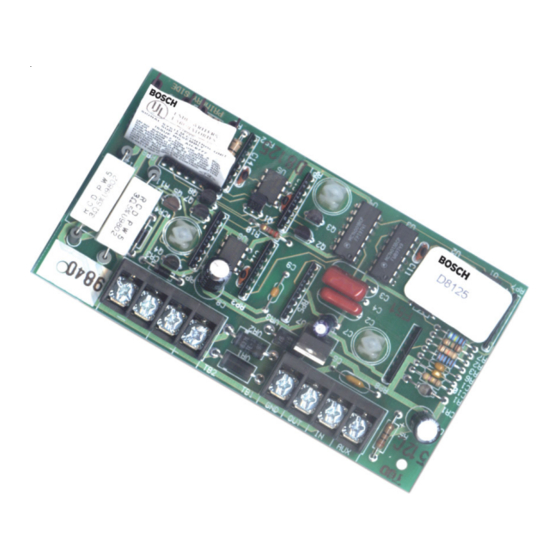
- Page 1 Zone Expansion Module D8125 Operation and Installation Guide...
- Page 2 D8125 D8125 Operation and Installation Guide 74-04247-000-N Page 2 © 2004 Bosch Security Systems, Inc.
-
Page 3: Table Of Contents
D8125, D8127 and D9127 POPIT Modules ....................... 12 2.3.1.1 Listings ....................................12 Non-G 9000 Series Point Expansion ..........................12 2.4.1 D8125 POPEX / D8127 and D9127 POPIT Modules ....................13 2.4.1.1 Listings ....................................13 D9112B1/D7212B1 Point Expansion ..........................13 2.5.2 D8125 POPEX Module / D8127 POPIT Modules ..................... - Page 4 D1252A POPIT Activity ..............................42 4.2.3 Missing POPIT Modules ..............................42 4.2.4 Extra POPIT Modules ................................. 43 4.2.5 Additional Troubleshooting Tips ............................43 Index ............................................ 45 D8125 Operation and Installation Guide 74-04247-000-N Page 4 © 2004 Bosch Security Systems, Inc.
- Page 5 Figures Figure 1: D8125 Jumper Setting ..............................15 Figure 2: POPEX Installation ................................17 Figure 3: Connecting the D8125 POPEX to the 9000 Series Panel .................. 19 Figure 4: Program Record Sheet ..............................20 Figure 5: D8125 Connections ................................ 21 Figure 6: Typical Expansion Loop/POPIT Configuration ......................
- Page 6 D8125 Contents Notes: D8125 Operation and Installation Guide 74-04247-000-N Page 6 © 2004 Bosch Security Systems, Inc.
-
Page 7: Introduction
See the following for a more complete and detailed description of the D8125 POPEX Zone Expansion. They have been included in the table below with their part number for easy ordering. Contact Bosch Security Systems if you need to order additional literature. -
Page 8: Documentation Conventions
If necessary, the installer should consult an experienced radio/television technician for additional suggestions, or send for the “Interference Handbook” prepared by the Federal Communications Commission. This booklet is available from the U.S. Government Printing Office. Washington D.C. 20402, stock no. 004-000-00450-7. D8125 Operation and Installation Guide 74-04247-000-N Page 8... -
Page 9: Overview
* A model “U” POPIT mounted within a tampered enclosure can be used in place of a model “T” POPIT. The following describe the classification of the Bosch Security Systems modules. Please reference the NFPA 72 for the specific details of IDC, SLC, NAC conditions. -
Page 10: D9412G/D7412G Point Expansion
POPITs connect to supervised two-wire data expansion loops run from POPIT to POPIT throughout the premises. Data expansion loops connect to a D8125 Point of Protection Expander (POPEX) Module. POPEX Modules connect to the point bus on the panel, Terminals 23 and 24 for power (3 and 9 on the D7412G), and Terminals 25 and 26 (D9412G only), or 27 and 28 for data. -
Page 11: D8125, D8127 And D9127 Popit Modules
D8125 POPEX/D8127 and D9127 POPIT Modules D8127 and D9127 POPITs use the D8125 POPEX Module to report to the panel. Each D8125 supports up to 119 POPIT points. Connect two D8125 Modules to the D9412G to bring the combined total number of POPIT and on-board points to 246. -
Page 12: D8125, D8127 And D9127 Popit Modules
D8125, D8127 and D9127 POPIT Modules D8127 and D9127 POPITs use the D8125 POPEX Module to report to the panel. The D8125 supports up to 32 POPIT points (Points 9 to 20). The panel only annunciates activity for each POPIT, not each detection device connected to the sensor loop. -
Page 13: D8125 Popex/ D8127 And D9127 Popit Modules
D8125 POPEX/ D8127 and D9127 POPIT Modules D8127 and D9127 POPITs use the D8125 POPEX module to report to the D9412/D9112. Each D8125 supports up to 119 POPIT points. Connect two D8125 modules to the D9412/D9112 to bring the combined total number of POPIT and on- board points to 246. -
Page 14: Listings
Expansion (ZONEX) system. The D8125 POPEX Module is a Point Of Protection EXpander. One or two POPEX Modules can be used to interface zone expansion loops to the D8112G series. Each POPEX Module can monitor up to 63 D8126/D8127 POPIT Modules, and as many as 126 individual POPIT Modules can be monitored in a ZONEX system with two POPEX Modules. -
Page 15: D9124 Point Expansion
D9412G/D7412G Point Expansion for details regarding Popit installation. You can connect up to four data expansion loops to one D8125 input at the motherboard. Data Loops 1 to 4 connect to the D8125 POPEX 1 input on the motherboard (Terminals 11 through 18). Data Loops 5 to 8 connect to the D8125 POPEX 2 input at the motherboard (Terminals 19 through 26). - Page 16 D8125 Overview Notes: D8125 Operation and Installation Guide 74-04247-000-N Page 16 © 2004 Bosch Security Systems, Inc.
-
Page 17: Installation
Installation D9412G/D7412G/D7212G, D9412/D9112/D7412/D7212 Save the POPIT Label Sheets: The D8125 is packaged with two sets of POPIT label sheets. One is marked for use with the D9412/D9112. Save this set. You will use it later to label the POPITs. 3. 1 . 1... -
Page 18: Wiring Popits To The Data Expansion Loop
There are two positive (+) and two negative (-) data expansion loop terminals on each POPEX module. Follow the procedure below to connect the data expansion loops to the D8125 POPEX Module (refer to Figure 3). Remember you can only connect a maximum of 119 POPITs to one D8125 on the D9412/D9112 and 67 for the D7412/D7212. -
Page 19: Figure 3: Connecting The D8125 Popex To The 9000 Series Panel
D8125 Installation Figure 3: Connecting the D8125 POPEX to the 9000 Series Panel D8125 Operation and Installation Guide © 2004 Bosch Security Systems, Inc. Page 19 74-04247-000-N... -
Page 20: Popit Module Point Assignments
POPEX #2. Two sheets of peel-off POPIT labels are supplied with the D8125 POPEX module. Use the sheet marked Bank1 for Points 9 to 127. Use the sheet marked Bank2 for Points 129 to 247. -
Page 21: Mounting
Wiring POPITs to the Data Expansion Loop You can connect up to 63 POPITs (40 maximum for a D7212B1) to each D8125 module. Use one 2-wire data expansion loop or distribute the POPITs on up to three loops. Setting DIP switches on the POPIT modules assigns them to point numbers. -
Page 22: Wiring Popits Together
There are two positive (+) and two negative (-) data expansion loop terminals on each POPEX module. Follow the procedure below to connect the data expansion loops to the D8125 POPEX Module. See Figure 5. Remember, you can only connect a maximum of 63 POPITs (40 for a D7212B1) to one D8125, Connect the positive (+) Data terminal from the first POPIT on the data expansion loop to one of the D8125 module’s positive (+) terminals. -
Page 23: Popit Sensor Loops
D9112B1/D7212B1. A ground on the sensor loop reports as an open condition. Each POPIT is programmed and transmits to the D9112B1/D7212B1 separately. Terminate each POPIT sensor loop with the 33 kΩ end-of-line resistor (Bosch Security Systems D106F) included with each POPIT. -
Page 24: Figure 8: Popit Label Placement For 9000 Series Control Panels
Security System Owner’s Manual (P/N: 74-06633-000) and the Security System User’s Guide (P/N: 71-06141-000) contain instructions for performing a walk test. If a point does not test, check the programming for a duplicated address. D8125 Operation and Installation Guide 74-04247-000-N Page 24 ©... -
Page 25: D8112G1/G2
Disconnect the battery by unhooking the positive (red) battery lead from the battery. Unplug the transformer. Reversed polarity damages the D8125. Make Figure 10: D8112G1/G2 POPEX Installation sure you correctly wire the D8125 AUX and GND terminals to the control panel. WARNING 3.3.2.2 Wiring Procedure Connect D8112G1/G2 Terminal 4 to the POPEX GND terminal (see Figure 11). -
Page 26: Popit Module Installation
The zone expansion loop is a two-conductor wire interconnecting all POPIT Modules assigned to a single POPEX (see Figure 11). Up to three zone expansion loops can be connected to one D8125 when using shielded or unshielded cable. The required wire gauge for the zone expansion loop(s) (up to three max.) can be determined using Table 6. When using unshielded cable each zone expansion loop can be up to the distance shown in Table 6. -
Page 27: Figure 11: D8112G1/G2 Popex And Popit Module Installation
D8125 Installation Figure 11: D8112G1/G2 POPEX and POPIT Module Installation D8125 Operation and Installation Guide © 2004 Bosch Security Systems, Inc. Page 27 74-04247-000-N... -
Page 28: Wiring Popits To A Popex Module
POPIT module. The maximum length of 22 AWG (0.8 mm) cable used for each sensor loop is determined by voltage drop. Bosch Security Systems recommends the use of twisted-pair wire in all POPEX-POPIT installations. If a noisy or unstable environment is suspected, or if a long sensor loop wire run is used, the cable must be shielded against AC induction. -
Page 29: Popex/Popit Configurations
• POPEX #1 assigns a maximum of 8 POPITs to a D8112G1/G2 zone (ex., Points 101-108). • POPEX #2 assigns an additional 8 POPITs maximum, to a D8112G1/G2 zone (ex., Points 109-116). • A maximum of 126 POPITs can be installed. D8125 Operation and Installation Guide © 2004 Bosch Security Systems, Inc. Page 29... - Page 30 I.D. code ZN104, “ZN1” indicates that the POPIT is assigned to master zone 100 of the D8112G1/G2 Control Panel, and “04” indicates that the POPIT reports as expansion point #4. D8125 Operation and Installation Guide 74-04247-000-N Page 30...
-
Page 31: Table 7: D8112G1/G2 Horizontal Mode - Popex And Popit Modules
ZN 516 ZN 616 ZN 716 USED POPEX #1 (D8112G1/G2 TERM 28) POPEX #1 (D8112G1/G2 TERM 28) Table 7: D8112G1/G2 Horizontal Mode - POPEX and POPIT Modules D8125 Operation and Installation Guide © 2004 Bosch Security Systems, Inc. Page 31 74-04247-000-N... -
Page 32: Table 8: D8112G1/G2 Vertical Mode - Popex And Popit Modules
ZN 516 ZN 616 ZN 716 USED POPEX #1 (D8112G1/G2 TERM 28) POPEX #1 (D8112G1/G2 TERM 27) Table 8: D8112G1/G2 Vertical Mode - POPEX and POPIT Modules D8125 Operation and Installation Guide 74-04247-000-N Page 32 © 2004 Bosch Security Systems, Inc. -
Page 33: Popit Displays
(Row of stars) ************** NOT READY TO ARM Standard display indicating an abnormal loop condition * This programmed display will appear for all points on this master zone. D8125 Operation and Installation Guide © 2004 Bosch Security Systems, Inc. Page 33 74-04247-000-N... -
Page 34: Central Station Reports
D6500 receiver. A RESTORAL ZONE D will, however, be sent when the expansion loop itself has restored. A complete list of reports received by the D6500 Receiver can be found in the D6500 Report Directory (P/N: 4998132019). D8125 Operation and Installation Guide 74-04247-000-N Page 34... -
Page 35: Local Status Test
MASTER ZONE 3: 6 2.8 Z4POINTS MASTER ZONE 4: 6 2.9 Z5POINTS MASTER ZONE 5: 6 2.10 Z6POINTS 2.11 Z7POINTS 2.12 Z8POINTS Figure 13: Operative ZONEX System D8125 Operation and Installation Guide © 2004 Bosch Security Systems, Inc. Page 35 74-04247-000-N... -
Page 36: Figure 14: Missing Popit
MASTER ZONE 3: 6 2.8 Z4POINTS MASTER ZONE 4: 6 EXTRA 2.9 Z5POINTS MASTER ZONE 5: 7 POPIT 2.10 Z6POINTS 2.11 Z7POINTS 2.12 Z8POINTS Figure 15: Extra POPIT D8125 Operation and Installation Guide 74-04247-000-N Page 36 © 2004 Bosch Security Systems, Inc. -
Page 37: Figure 16: Popit Switch Setting Error
2.8 Z4POINTS MASTER ZONE 4: 5 POPIT EXTRA 2.9 Z5POINTS MASTER ZONE 5: 7 POPIT 2.10 Z6POINTS 2.11 Z7POINTS 2.12 Z8POINTS Figure 17: POPIT Switch Setting Error D8125 Operation and Installation Guide © 2004 Bosch Security Systems, Inc. Page 37 74-04247-000-N... -
Page 38: Figure 18: Extra Popit Installed
2.9 Z5POINTS MASTER ZONE 5: 7 have same switch setting 2.10 Z6POINTS (EXTRA POPIT not displayed) 2.11 Z7POINTS 2.12 Z8POINTS Figure 19: POPIT Switch Setting Error D8125 Operation and Installation Guide 74-04247-000-N Page 38 © 2004 Bosch Security Systems, Inc. -
Page 39: Troubleshooting
Faulting the point a second time produces the tone and POINT TEXT displays the point text, but does not reduce the PTS TO TEST count. Figure 20: Service Walk Test Flowchart D8125 Operation and Installation Guide © 2004 Bosch Security Systems, Inc. Page 39 74-04247-000-N... -
Page 40: Problems With Points
Voltage should be 9 to 13 VDC at each POPIT. D8128C OctoPOPIT is installed at Install a D8125 POPEX and D9127 POPITs for Points 121-127 on the last address on the ZONEX ZONEX 1 and for Points 241-247 on ZONEX 2. - Page 41 POPIT loop is shorted beyond the programmed debounce time. Table 9 (cont’d): 9000 Series to D8125 POPEX Point Problems Troubleshooting D8125 Operation and Installation Guide © 2004 Bosch Security Systems, Inc. Page 41 74-04247-000-N...
-
Page 42: Extra Points
D8112G1/G2. Meter the data terminals of each POPIT to verify correct polarity (refer to Section 3.3.3 POPIT Module Installation), and a voltage of 9 VDC to 13 VDC. D8125 Operation and Installation Guide 74-04247-000-N Page 42 © 2004 Bosch Security Systems, Inc. -
Page 43: Extra Popit Modules
If the D1252A displays non-programmed information when a master zone is faulted, copy the D8112:PTEXT file for the non-expanded zone displaying the information, delete the information, and reload the file. D8125 Operation and Installation Guide © 2004 Bosch Security Systems, Inc. - Page 44 D8112G. Certain revision 17.07 D8112G Control/Communicators may not detect POPIT faults even when all programming and wiring has been properly completed. Bosch Security Systems has developed two solutions to this problem: 1). Restore all POPITs to a normal condition (close all doors and windows), and then disable and restart the system.
-
Page 45: Index
Zonex Expansion Description ..10 Zonex Expansion Description, Wiring D8125 POPIT Module ....13 D7212B1 ........ 13 D8125 to 9000 Series ..... 17 D8127 POPIT Module ....13 Zonex Expansion Description, D8125 to D7212B1 ......21 D7412G, Wiring POPITS to D8112G1/G2 ...... - Page 46 Data Expansion Loops Listings, D8125 ......14 Wiring Wiring POPITs ....... 18 Listings, D8127 ......14 D8125 to 9000 Series ..... 17 POPIT Labels POPEX Module, D8125 ....13 D8125 to D7212B1 ......21 Module Point Assignments ... 20 POPIT Module, D8127 ....13 D8125 to D8112G1/G2 ....
- Page 47 D8112G1/G2 ........28 D7212B1 Zonex Expansion D8112G1/G2 ......... 14 Module Point Assignments Description ......14 Other Literature Referenced D8125 to 9000 Series ..... 20 D9112B1 Zonex Expansion Introduction ......... 7 D8125 to D7212B1 ......23 Description ......14 Overview ............ 9 D8125 to D9112B1 ......
- Page 48 Troubleshooting ........39 Zone Expansion Description, Wiring POPITs together, D7212B1 Basic D8112G1/G2 ......14 Tampered POPITs 9000 Series to D8125 POPEX ..39 D8126 POPIT 3 inch clearance ......22 D8112G1/G2 ........42 Zone Expansion Description, Wiring POPITs together, D9112B1 Additional Tips .......
Need help?
Do you have a question about the D8125 and is the answer not in the manual?
Questions and answers