Table of Contents
Advertisement
Quick Links
1
APPLICATION ................................................................................... 3
2
DESCRIPTION (FIG. A) ..................................................................... 3
3
PACKAGE CONTENT LIST .............................................................. 3
4
SYMBOLS .......................................................................................... 4
5
GENERAL POWER TOOL SAFETY WARNINGS ............................ 4
5.1
Working area ............................................................................................................. 4
5.2
Electrical safety ......................................................................................................... 4
5.3
Personal safety ......................................................................................................... 5
5.4
Power tool use and care ........................................................................................... 5
5.5
Service ....................................................................................................................... 5
6
SAFETY EQUIPMENT ....................................................................... 6
6.1
Cleaving wedge ......................................................................................................... 6
6.2
Saw blade protector .................................................................................................. 6
6.3
Push stick .................................................................................................................. 6
7
UNPACKING AND ASSEMBLY ........................................................ 6
7.1
Assembly (Fig. 1) ...................................................................................................... 6
7.2
Attaching the tilt protection (Fig. 2) ......................................................................... 6
7.3
Fitting the parallel fence (Fig. 3) ............................................................................... 6
7.4
Mounting mitre angle stop (Fig. 4) ........................................................................... 7
7.5
Mounting the saw blade guard (Fig. 5) .................................................................... 7
7.6
Mounting the extraction hose (Fig. 6) ...................................................................... 7
8
OPERATION ...................................................................................... 7
8.1
Check before starting the device! ............................................................................ 7
8.2
Operating elements ................................................................................................... 7
8.2.1
On/off switch ............................................................................................................... 7
8.2.2
Overload Protection (18) ............................................................................................. 7
8.2.3
Setting mechanism for the tilt angle ............................................................................. 8
8.2.4
Hand crank for setting the cutting height ..................................................................... 8
8.3
Workpiece stops ....................................................................................................... 8
8.3.1
Mitre angle stop .......................................................................................................... 8
8.3.2
Mitre cuts (Fig. 7) ........................................................................................................ 8
Copyright © 2019 VARO
POWE51101
P a g e
| 1
EN
www.varo.com
Advertisement
Table of Contents

Related Manuals for Powerplus POWE51101


Summary of Contents for Powerplus POWE51101
-
Page 1: Table Of Contents
POWE51101 APPLICATION ................... 3 DESCRIPTION (FIG. A) ..............3 PACKAGE CONTENT LIST .............. 3 SYMBOLS ..................4 GENERAL POWER TOOL SAFETY WARNINGS ......4 Working area ......................4 Electrical safety ......................4 Personal safety ......................5 Power tool use and care ................... 5 Service ........................ - Page 2 POWE51101 8.3.3 Setting the stop rail of the parallel stop ................ 8 8.3.4 Parallel stop ........................ 8 Setting the cutting height (Fig. 8) ................8 Setting the saw blade angle (Fig. 8) ................. 9 Sawing ........................9 CLEANING AND MAINTENANCE ..........10 Cleaning and maintenance overview ..............
-
Page 3: Application
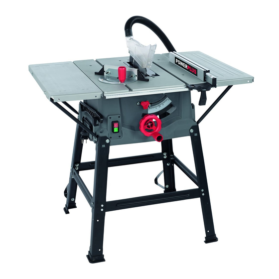
POWE51101 TABLE SAW 2200W POWE51101 1 APPLICATION The device is designed to cleave and-cross-cut solid wood, laminated wood, chipboard, wood core plywood and similar wooden materials. Round pieces may not be sawed as the rotating saw blade may cause them to roll. Only those materials may be processed for which the particular saw blade is designed. -
Page 4: Symbols
POWE51101 4 SYMBOLS The following symbols are used in this manual and/or on the machine: Denotes risk of personal Read manual before use. injury or damage to the tool. Conforms to essential safety standards of applicable Wear noise protection. European directives. -
Page 5: Personal Safety
POWE51101 Personal safety ▪ Stay alert, watch what you are doing and use common sense when operating a power tool. Do not use a power tool when you are tired or under the influence of drugs, alcohol or medication. A moment of inattention when operating a power tool may result in serious personal injury. -
Page 6: Safety Equipment
POWE51101 6 SAFETY EQUIPMENT Cleaving wedge The cleaving wedge (8) prevents a workpiece being caught by the ascending teeth and being thrown against the operator. The cleaving wedge must remain in place during operation. Saw blade protector The saw blade guard (7) protects the user from accidentally touching the saw blade and from flying splinters. -
Page 7: Mounting Mitre Angle Stop (Fig. 4)
POWE51101 Mounting mitre angle stop (Fig. 4) The mitre angle stop (11) consists of two parts - the stop plate (A) and the angle adjustment (B) that must be assembled together. ▪ Insert the stop plate (A) into the gaps of the angle adjustment (B) with both adjusting screws (C), push into the required position and tighten the adjusting screws. -
Page 8: Setting Mechanism For The Tilt Angle
POWE51101 8.2.3 Setting mechanism for the tilt angle The saw blade can be adjusted to any angle between 0° and 45°. Loosen the locking knob (3), press the lever (2) and turn to the desired tilt angle and tighten the locking knob (3). -
Page 9: Setting The Saw Blade Angle (Fig. 8)
POWE51101 ▪ Turning the hand crank counterclockwise reduces the cutting depth. Turning the hand crank clockwise Increases the cutting depth. Note: To balance out play in the cutting height setting, always raise the saw blade from below to the required position. -
Page 10: Cleaning And Maintenance
POWE51101 9 CLEANING AND MAINTENANCE Cleaning and maintenance overview Prior to each use What? How? Check the saw blade to ensure it is Changing the saw blade correctly positioned and fixed in place. Check the saw blade protector box for... -
Page 11: Fitting And Changing The Saw Blade (Fig. 9)
POWE51101 9.3.1 Fitting and changing the saw blade (Fig. 9) Caution! Unplug from power source. Caution! Ensure that the saw housing is well lit. ▪ Remove the screw (24) of the front of the table insert. ▪ Remove the table insert ▪... -
Page 12: Technical Data
We also disclaim all liability for any bodily injury resulting from inappropriate use of the tool. ▪ Repairs may only be carried out by an authorised customer service centre for Powerplus tools. ▪ You can always obtain more information at the number 00 32 3 292 92 90. -
Page 13: Environment
POWE51101 ▪ Acceptance of claims under warranty can never lead to the prolongation of the warranty period nor commencement of a new warranty period in case of a device replacement. ▪ Devices or parts which are replaced under the warranty therefore remain the property of Varo NV. -
Page 14: Declaration Of Conformity
POWE51101 15 DECLARATION OF CONFORMITY VARO N.V. - Joseph Van Instraat 9 - BE2500 Lier - BELGIUM, declares that, product: Table saw trade mark: PowerPlus model: POWE51101 is in conformity with the essential requirements and other relevant provisions of the applicable European Directives, based on the application of European harmonized standards.
Need help?
Do you have a question about the POWE51101 and is the answer not in the manual?
Questions and answers