Table of Contents
Advertisement
OWNER'S
MANUAL
MODEL NO.
C 151 61672 3
Caution:
Read and Follow
All Safety Rules
and Instructions
Before Operating
This Equipment
Sears Canada, Inc., Toronto, Ontario M5B 2B8
104739
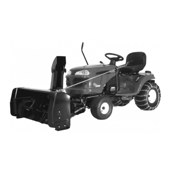
COMPACT
SNOWBLOWER 40" FOR
CRAFTSMAN TRACTORS
·Assembly
·Operation
·Maintenance
·Repair Parts
*104739*
1
TWO
STAGE
I-05
Advertisement
Table of Contents

Subscribe to Our Youtube Channel
Related Manuals for Sears CRAFTSMAN C 151 61672 3


Summary of Contents for Sears CRAFTSMAN C 151 61672 3
- Page 1 MODEL NO. C 151 61672 3 COMPACT STAGE SNOWBLOWER 40" FOR CRAFTSMAN TRACTORS Caution: ·Assembly Read and Follow ·Operation All Safety Rules ·Maintenance and Instructions ·Repair Parts Before Operating This Equipment Sears Canada, Inc., Toronto, Ontario M5B 2B8 *104739* 104739 I-05...
- Page 2 ON CRAFTSMAN TRACTOR ATTACHMENTS "SNOWBLOWER" For one (1) year from date of purchase, Sears Canada Inc. will repair or replace free of charge at Sears option any parts which are defective as a result of defective material or faulty workmanship.
-
Page 3: Table Of Contents
TABLE OF CONTENTS PAGE INTRODUCTION ............................... SAFETY PRECAUTIONS ..........................SAFETY DECALS ............................. ASSEMBLY Step 1: Tractor Preparation ........................Step 2: Subframe Installation ......................Step 3: Drive Mechanism Preparation ....................Step 4: Drive Mechanism Installation ....................Step 5: Snowblower Preparation ......................Step 6: Snowblower Installation ...................... -
Page 4: Introduction
INTRODUCTION TO THE PURCHASER This new accessory was carefully designed to give years of dependable service. This manual has been provided to assist in the safe operation and servicing of your accessory. NOTE: All photographs and illustrations in the manual may not necessarily depict the actual models or accessory but are intended for reference only and are based on the latest product information available at the time of publication. -
Page 5: Safety Precautions
SAFETY PRECAUTIONS Careful operation is your best insurance against an accident. Read this section carefully before operating the vehicle and accessory. This accessory is capable of amputating hands and feet and throwing objects. Failure to observe the following safety instructions could result in serious injury. All operators, no matter how experienced they may be, should read this and other manuals related to the vehicle and accessory before operating. - Page 6 SAFETY PRECAUTIONS 13.Never operate the accessory without good visibility OPERATION: or light. 1. Do not put hands or feet near, under or inside rotating parts. 14.Keep the accessory away from heat sources or flames. 2. Exercise extreme caution when operating on or crossing gravel drives, walks or roads.
-
Page 7: Safety Decals
SAFETY DECALS REPLACE IF DECALS ARE DAMAGED SEE PARTS BREAKDOWN FOR DECAL LOCATION Decal # 102124 Decal # 102125 Decal # 102126 Decal # 102127 Decal # 102128 Decal # 102815... -
Page 8: Assembly
ASSEMBLY IMPORTANT: TORQUE ALL BOLTS ACCORDING TO TORQUE SPECIFICATION TABLE (SEE TABLE CONTENTS) WHEN STATED: TIGHTEN FIRMLY. REFER PARTS BREAKDOWN SECTION FOR PARTS IDENTIFICATION. NOTE: This subframe was designed to fit various models of tractors. Make sure to follow the instructions that correspond to your tractor. -
Page 9: Step 2: Subframe Installation
ASSEMBLY STEP 2 SUBFRAME INSTALLATION: You must choose which brace pin (item 1 or item 4) that is appropriate for your tractor model. Tractors with a clutch that measures 5.5” high only (as shown): You must use brace pin (item 1) and install it in the bottom holes of the right support (item 2) with two carriage bolts 3/8’’... - Page 10 ASSEMBLY RIGHT SUPPORT: Install the right support (item 1) on the right side. The chart identifies the hardware according to the holes in the tractor’s frame. Even though some holes may not exist on certain models of tractors, use the maximum of holes &...
- Page 11 ASSEMBLY LEFT SUPPORT AND HANDLE SUPPORT: Install the left support (item 1) and the handle support (item 17). Secure the brace pin (item 19) The chart identifies the hardware according to the holes in the tractor’s frame. Even though some holes may not exist on certain models of tractors, use the maximum of holes &...
- Page 12 ASSEMBLY If necessary, slide the shim (item 20, previous page) between the tractor frame and the support, in line with hole (item 9 or item 11). (Make sure that the shim stays perpendicular with the top of the support). Slightly tighten the screws and bolts. Make sure that the brace pin stays straight and does not come into contact with any part of the tractor (ex: the engine belt when mower deck is in raised posi-...
- Page 13 ASSEMBLY TRACTORS WITH MANUAL CLUTCH ACTIVATED BY A CABLE: If it is not possible to put back in place the tractor’s belt guides, use the replacement belt guides supplied. Insert the collars (item 1) on the brace pin (item 4). Tighten slightly.
- Page 14 ASSEMBLY ASSEMBLY PIVOT SUPPORT: Turn the front wheels towards the right. Install the pivot support (item 1) between the two supports and slide in place the pin (item 2) in the required holes. The other holes get the hooked end (item 5) of the pin.
-
Page 15: Step 3: Drive Mechanism Preparation
ASSEMBLY LIFT MECHANISM: Slide the link (item 1) inside the box of the right support (item 2). Insert the pin (item 3) inside the link. Insert the lift arm (item 4) on the pin (item 5) of the right support and on the pin (item 3). Secure the arm with one washer (item 6) and one hair pin 4 mm (item 7). - Page 16 ASSEMBLY NOTE: If a bracket is installed on the outside of the lefthand side of the tractor frame: 1 Install the left support on the inside of the frame. Secure both bracket and left support to frame using hardware already mentionned. 2 Insert two flat washers 7/16’’...
- Page 17 ASSEMBLY Use the following instructions to reposition the support (item 1) as needed. To make the job easier, remove the spring (item 2). Remove the support (item 1) by removing the two hex. bolts 1/4’’ x 1/2’’ (item 3). Tractor Position 2006 (most models, factory installed) VGT frame...
- Page 18 ASSEMBLY TRACTOR WITH AN ELECTRIC CLUTCH. No modifications are needed. TRACTORS WITH MANUAL CLUTCH ACTIVATED BY A CABLE. Remove the spring that is hooked in holes (item1) of idler arm (item 2) and drive frame (item 10). Hook the spring of the tractor’s cable (item 5) on the tension arm.
-
Page 19: Step 4: Drive Mechanism Installation
ASSEMBLY STEP 4 DRIVE MECHANISM INSTALLATION: NOTE: You must remove mower deck to install the drive mechanism. Install the drive mechanism (item 1) by hooking the front part of the drive frame (item 2) on the brace pin (item 3). Lift and attach the rear portion of the drive frame between the supports (items 4 or 5 or 6) by inserting a pin on each side. - Page 20 ASSEMBLY When the drive mechanism is disengaged, the belt guides (item 4) must push enough on the belt (item 3) so that the drive mechanism pulley does not turn. Tighten the collar screw and the nut tightly. NOTE: After installation, attach the cable to the frame with the new tie wrap supplied with this kit.
-
Page 21: Step 5: Snowblower Preparation
ASSEMBLY STEP 5 SNOWBLOWER PREPARATION: Install the rotation ring (item 2) over opening (item 3) as shown and align the notches. Place the chute (item 1) (facing the rear) and clip the back over the rotation ring then turn the chute towards the front to lock into place. -
Page 22: Step 6: Snowblower Installation
ASSEMBLY STEP 6 SNOWBLOWER INSTALLATION: Refer parts breakdown section parts identification. WARNING TO PREVENT INJURIES: Stop the motor. Apply parking brake. Remove the ignition key. Disconnect the wire from the spark plug(s) and keep away from spark plug(s) to prevent accidental starting. - Page 23 ASSEMBLY Insert the handgrip (item 1) on the handle (item 2). Insert the handle (item 2) through the support (item 3) as shown. Insert the handle (item 2) on the rotation worm (item 5) and secure with a 2.5 mm. hair pin (item 4). Install handle VERIFY SKID SHOE ADJUSTMENT: LEVEL PAVED SURFACE: Adjust skid shoes to allow...
-
Page 24: Operation
OPERATION SNOWBLOWER OPERATION WARNING a) Make sure the snowblower is clear of snow -Do not attempt to clear plugged chute, auger or before engaging the snowblower. fan of snow while tractor engine is running. -Disengage snowblower. b) Make sure that the auger and impeller operate -Lower snowblower onto ground. -
Page 25: Maintenance
MAINTENANCE BEFORE DOING ANY MANTENCE OR CUTTING EDGE MAINTENANCE DISMOUNTING AN ACCESSORY, REFER TO THE SAFTEY PRECAUTIONS. Verify from time to time the wear on the cutting edge to make sure you do not wear out the base of the MAINTENANCE snowblower’s chassis. -
Page 26: Belt Installation, Adjustment & Replacement
MAINTENANCE BELT INSTALLATION, ADJUSTMENT, AND REPLACEMENT: SNOWBLOWER BELT: a) Lower the snowblower to the ground. b) Remove the belt guard. c) Loosen the knob (item 10) of the bearing support (item 11). d) Install the belt as shown. Belt installation Item 1: Snowblower pulley Item 2: V pulley Item 3: Tension arm... - Page 27 MAINTENANCE f) Apply tension to the belt by pulling up the tension WARNING arm (item 1). After installation of the snowblower belt, make sure there is enough tension on the belt. To obtain TO PREVENT INJURIES: the proper tension, the distance between the coils It is the person who installs the drive mechanism of the spring should be .25’’...
-
Page 28: Dismounting
DISMOUNTING DRIVE MECHANISM DISMOUNTING SNOWBLOWER DISMOUNTING a) Dismount the snowblower. WARNING b) Remove the rear counterweight when you remove the front attachment. TO PREVENT INJURIES: Stop the motor. c) Dismount the drive mechanism by supporting it in hand and removing the pins. Carefully lower to the Apply parking brakes. -
Page 29: Troubleshooting
TROUBLESHOOTING PROBLEM POSSIBLE CAUSES CORRECTIVE ACTION Auger stops turning. Nylon shear pin is probably broken. Replace shear pin (for identification, see parts list "Snowblower"). The reduction chain is broken or the Remove both chain guards. Inspect & repair connecting link is unlocked. chain if needed (for identification, see parts list "Snowblower"). - Page 30 TROUBLESHOOTING PROBLEM POSSIBLE CAUSES CORRECTIVE ACTION Belt shredding Alignment Verify alignment of belt. Make sure belt is feeding well into pulleys. If not, adjust pulleys properly. Belt slips Worn springs Verify if springs are stretched from use and replace. Improper tension Increase tension on belt.
- Page 31 TROUBLESHOOTING PROBLEM POSSIBLE CAUSES CORRECTIVE ACTION Chute plugs easily. Tractor engine turning too slowly. Run engine at full throttle during snowblowing operation. Advancing too quickly with tractor. Allow snowblower to ingest snow at its own speed. Chute rotation is difficult. Dirt or ice may be underneath Dismount chute by removing the chute.
-
Page 32: Chute With Rotation System
PARTS BREAKDOWN / NOMENCLATURE DES PIÈCES CHUTE WITH ROTATION SYSTEM / GOULOTTE AVEC SYSTÈME DE ROTATION... - Page 33 PARTS LIST / LISTE DES PIÈCES REF. DESCRIPTION DESCRIPTION PART # RÉF. QTÉ PIÈCE # Rotation ring Coussinet de rotation 102756 Chute Goulotte 102748 Knob Bouton 102020 Carriage bolt 5/16" n.c. x 3/4" Boulon à carrosserie 5/16" n.c. x 3/4" STD533107 Nylon flat washer 7/16"...
-
Page 34: Drive Mechanism
PARTS BREAKDOWN / NOMENCLATURE DES PIÈCES DRIVE MECHANISM COMPACT MÉCANISME D’ENTRAINEMENT COMPACT... - Page 35 PARTS LIST / LISTE DES PIÈCES Ref. English description Description française Qty. Part # Réf. Qté. Pièce # 1 Drive frame Châssis d'entraînement 104343 2 Idler arm Bras de tension 104347 3 Cable holder Fixation du câble 104092 4 Support Support 104344 5 Support...
-
Page 36: Snowblower
PARTS BREAKDOWN / NOMENCLATURE DES PIÈCES SNOWBLOWER / SOUFFLEUSE... - Page 37 PARTS LIST / LISTE DES PIÈCES REF. PART # DESCRIPTION DESCRIPTION RÉF. QTÉ PIÈCE # Frame Châssis 103000 Bearing Roulement à billes 102757 Bearing Roulement à billes 102758 Éventail 102743 Retaining ring Bague de retenue 102760 Main drive pulley inc. 102784 Poulie d'entraîn.
- Page 38 PARTS LIST / LISTE DES PIÈCES REF. PART # DESCRIPTION DESCRIPTION RÉF. QTÉ PIÈCE # Tapping screw 1/4"-14 x 1/2" Vis taraudeuse 1/4"-14 x 1/2" Flat pulley Poulie plate 102765 Hex. bolt 3/8" n.c. x 1 1/2" Boulon hex. 3/8" n.c. x 1 1/2" Spring Ressort 102861...
- Page 39 PARTS LIST / LISTE DES PIÈCES REF. PART # DESCRIPTION DESCRIPTION RÉF. QTÉ PIÈCE # Hex. bolt 1/4" n.c. x 3/4" Boulon hex. 1/4" n.c. x 3/4" Bracket Fixation 104737 Hex. bolt 1/2" n.c. x 1 3/4" Boulon hex. 1/2" n.c. x 1 3/4" Bushing Coussinet 102225...
-
Page 40: Subframe
PARTS BREAKDOWN / NOMENCLATURE DES PIÈCES SUBFRAME / SOUS-CHÂSSIS... - Page 41 PARTS LIST / LISTE DES PIÈCES Ref. English description Description française Qty. Part # Réf. Qté. Pièce # 1 Right support Support droit 104332 2 Lift arm Bras de relevage 104336 3 Left support Support gauche 104331 4 Brace pin Tige de renfort 104334 5 Link...
- Page 42 PARTS LIST / LISTE DES PIÈCES Ref. English description Description française Qty. Part # Réf. Qté. Pièce # 40 Belt guide Guide courroie 104348 41 Collar Collet 104349 42 Machine screw P.H.#10 x 24 x 3/4" Vis mécanique P.H..#10 x 24 x 3/4" STD511007 43 Nylon insert lock nut #10 x24 Écrou à...
-
Page 43: Torque Specification Table
TORQUE SPECIFICATION TABLE GENERAL TORQUE SPECIFICATION TABLE USE THE FOLLOWING TORQUES WHEN SPECIAL TORQUES ARE NOT GIVEN NOTE: These values apply to fasteners as received from supplier, dry or when lubricated with normal oil. They do not apply if special graphited or moly disulphide greases or other extreme pressure lubricants are used. This applies to both UNF and UNC threads. -
Page 44: Attachments & Options
ATTACHMENTS & OPTIONS ROTARY BROOM #700381 with polypropylene brush. COUNTERWEIGHT UTILITY BLADE #61913 Fits on same subframe as snowblower & utility blade #700266 Required for safety and traction. Mounts on the same subframe as the Requires adaptor #700379 Counter-balances weight of snowblower &... -
Page 45: Consumer Information
_______________________________________________________________________________________________ Pour service en francais: 1-800-LE-FOYER (1-800-533-6937) www.sears.ca ®/TM Trademarks of Sears, Roebuck and Co. used under license by Sears Canada ® Marque deposée/ Marque de commerce de Sears, Roebuck and Co. utilisée en vertu d’une licence de Sears Canada... - Page 46 NOTES...
Need help?
Do you have a question about the CRAFTSMAN C 151 61672 3 and is the answer not in the manual?
Questions and answers