Table of Contents
Advertisement
OWNER'S
MANUAL
MODEL NO.
944.528241
Caution:
Read and fol low
all Safety Rules
and In struc tions
Be fore Op er at ing
This Equip ment
Sears Canada, Inc., Toronto, Ontario M5B 2B8
800 SERIES B&S ENGINE
24" TWO-STAGE
POWER-PROPELLED
SNOW THROWER
• Assembly
• Operation
• Maintenance
• Service and Adjustments
• Repair Parts
Advertisement
Table of Contents

Related Manuals for Sears Craftsman 800 Series


Summary of Contents for Sears Craftsman 800 Series
- Page 1 24" TWO-STAGE all Safety Rules POWER-PROPELLED and In struc tions Be fore Op er at ing SNOW THROWER This Equip ment • Assembly • Operation • Maintenance • Service and Adjustments • Repair Parts Sears Canada, Inc., Toronto, Ontario M5B 2B8...
-
Page 2: Safety Rules
IMPORTANT Safe Operation Practices for Walk-Behind Snow Throwers This snow thrower is capable of amputating hands and feet and throwing objects. Failure to observe the following safety instructions could result in serious injury. WARNING: Snow throwers have ex- Look for this symbol to point out im- posed rotating parts, which can cause por tant safety precautions. -
Page 3: Table Of Contents
6. When cleaning, repairing or inspecting the snow thrower, 16. Never touch a hot engine or muffler. stop the engine and make certain the collector/impel- ler and all moving parts have stopped. Disconnect Clearing a Clogged Discharge Chute the spark plug wire and keep the wire away from the Hand contact with the rotating impeller inside the discharge plug to prevent someone from accidentally starting the chute is the most common cause of injury associated with... -
Page 4: Warranty
LIMITED TWO (2) YEAR WARRANTY ON CRAFTSMAN SNOW THROWER For two (2) years from date of purchase Sears Canada, Inc. will repair or replace, at Sears option, free of charge parts which are defective as a result of material or workmanship. -
Page 5: Assembly / Pre-Operation
PARTS PACKED SEPARATELY IN CARTON (1) FUEL STABILIZER PACKET (1) POWER CORD (198563) (1) SAFTEY IGNITION KEY (1) AUGER CONTROL ROD (193071) (1) TRACTION DRIVE CONTROL ROD (1) MULTI- (1) DISCHARGE CHUTE WRENCH (180684) EXTRA SHEAR BOLTS AND NUTS (2) SHEAR BOLTS 1/4-20 x 1-3/4 (2) SPACERS (2) LOCKNUTS (198636) - Page 6 ASSEMBLY / PRE-OPERATION NOTE: The multi-wrench may be used for assembly of the INSTALL TRACTION DRIVE CONTROL ROD chute rotator head to snow thrower and making ad just ments (See Figs. 3 and 4) to the skid plates. The traction drive control rod has the long loop on the end of the spring as shown.
- Page 7 ASSEMBLY / PRE-OPERATION INSTALL AUGER CONTROL ROD (See Figs. 5 and 6) INSTALL DISCHARGE CHUTE / CHUTE ROTATOR HEAD (See Fig. 7) The auger control rod has the short loop on the end of the spring as shown. NOTE: The multi-wrench provided in your parts bag may be used to install the chute rotator head.
-
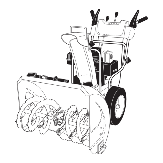
Page 8: Operation
OPERATION KNOW YOUR SNOW THROWER READ THIS OWNER'S MANUAL AND ALL SAFETY RULES BEFORE OPERATING YOUR SNOW THROWER. Compare the illustrations with your snow thrower to familiarize yourself with the location of various controls and adjustments. Save this manual for future reference. These symbols may appear on your snow thrower or in literature supplied with the product. - Page 9 OPERATION DISCHARGE GAS O LINE ELECTRIC TRACTION AUGER CHUTE DRIVE FILLER CAP START BUTTON DRIVE CONTROL CONTROL SPEED CONTROL LEVER LEVER CON TROL RECOIL LEVER MUF FLER LEVER (AUXILIARY) STARTER HANDLE CHUTE CHOKE DE FLEC TOR CON- TROL PRIM ER SAFETY IGNITION ON / OFF...
- Page 10 OPERATION The operation of any snow thrower can result The DISTANCE that snow is thrown is controlled by the in foreign objects thrown into the eyes, which position of the chute deflector. Set the deflector low to can result in severe eye damage. Always wear throw snow a short distance;...
- Page 11 OPERATION USING THE CLEAN-OUT TOOL (See Fig. 13) CAUTION: Do not move speed con trol le ver In certain snow conditions, the discharge chute may be- when traction drive control lever is en gaged. come clogged with ice and snow. Use the clean-out tool Damage to the snow thrower can result.
- Page 12 OPERATION HIGH POSITION CHOKE GAS O LINE ENGINE OIL (LOW GROUND CONTROL FILLER CAP FILL CAP / DIPSTICK CLEARANCE) AUGER HOUSING STARTER SCRAPER BAR BUTTON SKID PLATE NUTS LOW POSITION (HIGH GROUND CLEAR ANCE) FIG. 15 SCRAPER BAR (See Fig. 15) The scraper bar is not adjustable, but is reversible.
- Page 13 OPERATION 6. When the engine starts, release the recoil starter han dle TO START ENGINE and slowly move the choke control to the “OFF” posi- Your snow thrower engine is equipped with both a 120 Volt tion. A.C. electric starter and a recoil starter. The electric starter Allow the engine to warm up for a few minutes.
-
Page 14: Maintenance
MAINTENANCE GENERAL REC OM MEN DA TIONS LUBRICATION CHART The warranty on this snow thrower does not cover items that have been sub ject ed to operator abuse or negligence. SAE 5W-30 Motor Oil To receive full value from the warranty, operator must maintain snow thrower as in struct ed in this manual. -
Page 15: Maintenance Schedule
MAINTENANCE AUGER GEAR CASE NOTE: The left side wheel may be removed from snow thrower for easier access to the oil drain plug and place- • The gear case was filled with lubricant to the proper ment of a suitable container. The unit tilted, resting on the level at the factory. -
Page 16: Service And Adjustments
SERVICE AND ADJUSTMENTS WARNING: To avoid serious injury, before performing any service or ad just ments: 1. Be sure the on/off switch is in the OFF position. 2. Remove safety ignition key. 3. Make sure the augers and all mov ing parts have completely stopped. 4. - Page 17 10. Install clutch rod in swing plate; secure with hairpin. and should be replaced by original equipment man u fac tur er (OEM) belts avail able from your nearest Sears service 11. Place auger belt around and inside the groove of auger centre/department.
-
Page 18: Storage
HOLE the factory high speed setting can be dangerous and will void the warranty. If you think the engine-governed high speed needs adjusting, contact a Sears or other qualified WHEEL WHEEL HUB service centre, which has proper equipment and experience to make any necessary ad just ments. -
Page 19: Troubleshooting
• If possible, store your snow thrower indoors and cover it to protect it from dust and dirt. TROUBLESHOOTING See appropriate section in manual unless directed to a Sears service centre/department. PROBLEM CAUSE CORRECTION Does not start 1. -
Page 20: Repair Parts
SNOW THROWER - - MODEL NUMBER 944.528241 REPAIR PARTS AUGER HOUSING / IMPELLER ASSEMBLY 2 (EXPLODED) 01.07.004-B... - Page 21 SNOW THROWER - - MODEL NUMBER 944.528241 REPAIR PARTS AUGER HOUSING / IMPELLER ASSEMBLY PART DESCRIPTION 175321X479 IMPELLER 196710 GEARBOX ASSEMBLY 188909 BEARING 191079 IMPELLER PULLEY 175322 DISCHARGE BASE 178675X008 CORNER BRACKET 192199 CLEAN OUT TOOL 405400 TOOL CLIP 73800400 NUT 1/4−20 74780426 SCREW 1/4−20 X .625...
- Page 22 SNOW THROWER - - MODEL NUMBER 944.528241 REPAIR PARTS AUGER HOUSING / IMPELLER ASSEMBLY PART DESCRIPTION 404928X558 AUGER HOUSING 404931X479 SCRAPPER BAR 72270505 CARRIAGE BOLT 5/16−18 X .625 155377 NUT 5/16−18 3 (5x) 4 (5x) 01.07.001-A PART DESCRIPTION 405985X479 AUGER 24 LH 405986X479 AUGER 24 RH 01.07.008-A...
- Page 23 SNOW THROWER - - MODEL NUMBER 944.528241 REPAIR PARTS AUGER HOUSING / IMPELLER ASSEMBLY PART DESCRIPTION 01.11.001-A 174762X479 SKID PLATE LH 178777X479 SKID PLATE RH 72270506 CARRIAGE BOLT 5/16−18 X .75 751153 NUT 5/16−18 PART DESCRIPTION 174658 AUGER BEARING 01.07.005-A 411939 BEARING PLUG 179582...
- Page 24 SNOW THROWER - - MODEL NUMBER 944.528241 REPAIR PARTS CONTROL PANEL / DISCHARGE CHUTE PART DESCRIPTION 404770X558 CHUTE WELDMENT 178633X558 DEFLECTOR WELDMENT 420325 DEFLECTOR SEAL 179096X479 STRAP 189713X428 KNOB BLACK 128415 POP RIVET 185600 SHOULDER BOLT 1/4−20 X .704 72270505 CARRIAGE BOLT 5/16−18 X .625 01.09.001-A 191730...
- Page 25 SNOW THROWER - - MODEL NUMBER 944.528241 REPAIR PARTS CONTROL PANEL / DISCHARGE CHUTE PART DESCRIPTION 420337 LEVER/CABLE ROTATOR ASSEMBLY 01.09.007-A 17501010 SCREW 10−24 X .625 420678 ROTATOR HEAD 420677 ROTATOR PIVOT BRACKET 420675 PULLEY PIVOT 420674 CABLE ASSEMBLY NOTES: 1.
- Page 26 SNOW THROWER - - MODEL NUMBER 944.528241 REPAIR PARTS HANDLES PART DESCRIPTION 419800X479 PLOW HANDLE LH 419801X479 PLOW HANDLE RH 196944 PANEL BRACKET LH 196943 PANEL BRACKET RH 199513 HANDLE GRIP 74780512 SCREW 5/16−18 X .750 74780524 SCREW 5/16−18 X 1.50 751153 NUT 5/16−18 155415...
- Page 27 SNOW THROWER - - MODEL NUMBER 944.528241 REPAIR PARTS HANDLES 01.08.002-D PART DESCRIPTION 412683X479 CONTROL PANEL 412681X479 CONTROL LEVER LH 412682X479 CONTROL LEVER RH 412679X008 TRACTION ROD ARM 420889X004 IMPELLER ROD ARM 412677 INTERLOCK ROD 412680 SPACER 169675 RETAINER 17060408 SCREW 1/4−20 X .50 414280 KNOB BLACK...
- Page 28 SNOW THROWER - - MODEL NUMBER 944.528241 REPAIR PARTS HANDLES PART DESCRIPTION 180480 IMPELLER ROD ASSEMBLY 405740 TRACTION ROD ASSEMBLY 180445 SHIFTER ROD TOP 187716 SHIFTER ROD BOTTOM 180447 SPRING SLEEVE 178669 IMPELLER SPRING 180926 TRACTION SPRING 72270506 CARRIAGE BOLT 5/16−18 X .75 155377 NUT 5/16−18 169675...
- Page 29 SNOW THROWER - - MODEL NUMBER 944.528241 REPAIR PARTS HANDLES PART DESCRIPTION 419797X479 LOWER HANDLE 405784X479 PIVOT SUPPORT WELDMENT 150078 SCREW 5/16−18 X .750 17000616 SCREW 3/8−16 X 1.00 01.05.002-B PART DESCRIPTION 183352 CONSOLE PANEL 184471 SCREW 10−24 X .625 175262 SCREW 10−24 X 1.25 01.10.001-A...
- Page 30 SNOW THROWER - - MODEL NUMBER 944.528241 REPAIR PARTS DRIVE ITEM 43 EXPLODED 51 52 01.02.003-C...
- Page 31 SNOW THROWER - - MODEL NUMBER 944.528241 REPAIR PARTS DRIVE PART PART DESCRIPTION DESCRIPTION 198474 SPEED SELECTOR ASSEMBLY 12000007 E−RING .375 184471 SHOULDER SCREW 17501010 SCREW 10−24 X .625 402685X558 END PLATE 410877 BOTTOM PAN 17490508 SCREW 5/16−18 X .50 413429X479 SPRING BRACKET 57079...
- Page 32 SNOW THROWER - - MODEL NUMBER 944.528241 REPAIR PARTS DRIVE PART 01.03.005-A DESCRIPTION 188226 (assy of 1a,1b) AXLE ASSEMBLY 179352 AXLE SHAFT 9465M1 ROLL PIN 3/16 402691 SPROCKET 174697 THRUST WASHER 179830 BEARING 146315 SCREW 5/16−18 X .625 17490508 BOLT 5/16−18 X .500 155443 CLIK PIN 189282...
- Page 33 SNOW THROWER - - MODEL NUMBER 944.528241 REPAIR PARTS CHASSIS / PULLEYS PART DESCRIPTION - - - - - B&S MOTOR MODEL 12A113-0938-E8 409346X558 FRAME 417015X558 ENGINE MOUNT PLATE 150406 BOLT 3/8−16 150078 SCREW 5/16−18 X .750 01.00.007-A PART DESCRIPTION 192213 BELT COVER 179157...
- Page 34 SNOW THROWER - - MODEL NUMBER 944.528241 REPAIR PARTS WHEELS PART DESCRIPTION 187831X417 WHEEL ASSEMBLY LH 187866X417 WHEEL ASSEMBLY RH 01.06.001-A NOTE: All component dimensions given in U.S. inches. 1 inch = 25.4 mm IMPORTANT: Use only Original Equipment Manufacturer (O.E.M.) replacement parts. Failure to do so could be hazardous, damage your snow thrower and void your warranty.
- Page 35 SNOW THROWER - - MODEL NUMBER 944.528241 REPAIR PARTS BAG OF PARTS PART DESCRIPTION 198563 POWER CORD 169675 RETAINER PIN 180684 WRENCH 73800600 LOCKNUT 3/8−16 19131316 WASHER 3/8 198636 SHEAR BOLT 1/4−20 X 1−3/4 198638 SPACER 73800400 LOCKNUT 1/4−20 01.14.004-A PART DESCRIPTION 193071...
- Page 36 SNOW THROWER - - MODEL NUMBER 944.528241 REPAIR PARTS DECALS PART DESCRIPTION 181037 DECAL, DANGER 421327 DECAL, CRAFTSMAN 181035 DECAL, DANGER, DEFLECTOR 181042 DECAL, DANGER 421328 DECAL, CRAFTSMAN 181033 DECAL, INSTRUCTION 415391 DECAL, TRACTION LEVER 415390 DECAL, AUGER LEVER 415475 DECAL, SPEED CONTROL 421462 OWNER’S MANUAL, ENGLISH...
- Page 37 BRIGGS & STRATTON 4-CYCLE EN GINE MODEL NUMBER 12A113-0938-E8 307B 307A 1029 1022 1034 1026 914A 1023 1022 914B...
- Page 38 BRIGGS & STRATTON 4-CYCLE EN GINE MODEL NUMBER 12A113-0938-E8 1230 633A 604A 121 CARBURETOR OVERHAUL KIT 127A 977 CARBURETOR GASKET SET 633A 633A...
- Page 39 BRIGGS & STRATTON 4-CYCLE EN GINE MODEL NUMBER 12A113-0938-E8 1036 EMISSIONS LABEL 1005 1070 1210 677A 1252 1211 1251A 1251 1347 1252A 1196A 731A 1196 358 ENGINE GASKET SET 1095 VALVE GASKET SET 1022 1022...
- Page 40 BRIGGS & STRATTON 4-CYCLE EN GINE MODEL NUMBER 12A113-0938-E8 PART PART DESCRIPTION DESCRIPTION 699510 Cylinder Assembly 692317 Connector-Hose 399269 Kit-Bushing/Seal 791874 Line-Fuel (Molded) 299819 • Seal-Oil (Magneto Side) 699479 Screw (Control Bracket) 699486 Head-Cylinder 699220 Screw (Fuel Tank) 698210 +• Gasket-Cylinder Head 694543 Adjuster-Rocker Arm 695745...
- Page 41 BRIGGS & STRATTON 4-CYCLE EN GINE MODEL NUMBER 12A113-0938-E8 PART PART DESCRIPTION DESCRIPTION 692653 Spring/Link-Mechanical Governor 1022 691890 +• Gasket-Rocker Cover 693867 ؇ Seal-Throttle Shaft 1023 499924 Cover-Rocker Arm 633A 691321 ؇ Seal-Throttle Shaft 1026 790287 Rod-Push 692927 Boot-Spark Plug 1029 691230 Arm-Rocker...
- Page 42 SERVICE NOTES...
- Page 43 SERVICE NOTES...
- Page 44 02488 421462 08.13.08 TH Printed in U.S.A.
Need help?
Do you have a question about the Craftsman 800 Series and is the answer not in the manual?
Questions and answers