Table of Contents
Advertisement
OWNER'S MANUAL
Model Number
C 151 61822 4
* ASSEMBLY
* OPERATION
* MAINTENANCE
* REPAIR PARTS
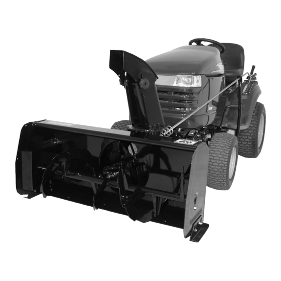
Compact 2 Stage Snowblower 40"
with Electric Lift
for
CRAFTSMAN TRACTORS
Sears Canada Inc.
Toronto, Ontario
M5B 2B8
WARNING:
READ & FOLLOW ALL SAFETY RULES & INSTRUCTIONS BEFORE
OPERATING YOUR EQUIPMENT
*107297*
107297_EN
R-07152015
1
Advertisement
Table of Contents

Related Manuals for Sears C 151 61822 4


Summary of Contents for Sears C 151 61822 4
- Page 1 OWNER’S MANUAL Model Number C 151 61822 4 * ASSEMBLY * OPERATION * MAINTENANCE * REPAIR PARTS Compact 2 Stage Snowblower 40" with Electric Lift CRAFTSMAN TRACTORS Sears Canada Inc. Toronto, Ontario M5B 2B8 WARNING: READ & FOLLOW ALL SAFETY RULES & INSTRUCTIONS BEFORE...
- Page 2 LIMITED ONE (1) YEAR WARRANTY ON CRAFTSMAN TRACTOR ATTACHMENTS For one (1) year from date of purchase, Sears Canada Inc. will repair or replace free of charge at Sears option any parts which are defective as a result of defective material or faulty workmanship.
-
Page 3: Table Of Contents
TABLE OF CONTENTS PAGE INTRODUCTION ..............................SAFETY PRECAUTIONS ............................SAFETY DECALS ..............................ASSEMBLY Tools Required ............................Step 1: Subframe Installation ........................Step 2: Subframe Preparation ........................Step 3: Installation of the Winch Control Switch ..................Step 4: Drive Mechanism Installation ......................Step 5: Snowblower Preparation ....................... -
Page 4: Introduction
INTRODUCTION TO THE PURCHASER This new accessory was carefully designed to give years of dependable service. This manual has been provided to assist in the safe operation and servicing of your attachment. NOTE: All photographs and illustrations in the manual may not necessarily depict the actual models or attachment, but are intended for reference only and are based on the latest product information available at the time of publication. -
Page 5: Safety Precautions
SAFETY PRECAUTIONS Careful operation is your best insurance against an accident. Read this section carefully before operating the vehicle and accessory. This accessory is capable of amputating hands and feet and throwing objects. Failure to observe the following safety instructions could result in serious injury. All operators, no matter how experienced they may be, should read this and other manuals related to the vehicle and accessory before operating. - Page 6 SAFETY PRECAUTIONS OPERATION: MAINTENANCE AND STORAGE Do not put hands or feet near, under or inside rotating parts. When cleaning, repairing or inspecting the vehicle and accessory: stop the engine, set brake, remove Exercise extreme caution when operating on or ignition key, and wait that all moving parts have crossing gravel drives, walks or roads.
-
Page 7: Safety Decals
SAFETY DECALS REPLACE IF DECALS ARE DAMAGED SEE PARTS BREAKDOWN FOR DECAL LOCATION DECAL #105130 DECAL #105126 To avoid serious injury: Keep hands, feet & clothing away from rotating auger Before installing or using: while engine is running. Locate, read and make sure to understand all of the owner’s manual. -
Page 8: Assembly
ASSEMBLY IMPORTANT: TORQUE ALL BOLTS ACCORDING TO TORQUE SPECIFICATION TABLE WHEN STATED: TIGHTEN FIRMLY. THE WINCH KIT IS TO BE USED ONLY TO LIFT BERCO ACCESSORIES, ANY OTHER USE MAY CAUSE DAMAGE TO THE VEHICLE. This subframe may be used to install different TOOLS REQUIRED: attachments (see attachments page). -
Page 9: Step 1: Subframe Installation
ASSEMBLY STEP 1 SUBFRAME INSTALLATION: Refer to parts breakdown section for parts identification. Install the supports (item 5) on each side of the vehicle. Item # Description Action Carriage bolt, Insert as shown. 3/8 x 1’’ (qty 6) Carriage bolt, Insert as shown. - Page 10 ASSEMBLY Install the spring (item 1) # Item Description Action Spring Install the spring on the frame as shown. NOTE: The latch must move freely. Install the spring as shown NOTE: Use these same instructions for both sides of tractor. Manual Clutch: Install the new belt guides (item A) that are included with the drive mechanism on the bottom carriage bolt (item 1).
-
Page 11: Step 2: Subframe Preparation
ASSEMBLY STEP 2 SUBFRAME PREPARATION: Step A : Remove the bolts and nuts holding the winch to the female hitch assembly. (item 1) Step B : Install the winch on the female hitch using the bolts 5/16” x 1-1/4” GR8 as illus- trated (1). -
Page 12: Step 3: Installation Of The Winch Control Switch
ASSEMBLY STEP 3: INSTALLATION OF THE WINCH CONTROL SWITCH Install the relay (item 1). Description Action Item Relay Install in an appropriate area. Metal screw Secure relay in place. #12 x 3/4’’ (qty 4) Nylon tie wrap 8’’ See * (qty 4) *If necessary use the nylon tie wraps to secure the Install the relay... - Page 13 ASSEMBLY CONNECTING THE WIRES NOTE: The posts on the relay are identified by numbers. (1-2-3-4). Install the wires from the winch on the posts of the relay. Red wire (+) on post #3. Black wire (-) on post #4. Connect the red wire from the winch (limit switch) with the green wire from the relay.
- Page 14 ASSEMBLY CAUTION FOR YOUR SECURITY: Read and follow the safety precautions for the battery in the vehicle’s manual. CONNECT THE WIRES ON THE BATTERY: Connect the wires from the relay to the vehicle’s battery. The red wire (+) on the positive post of the battery (item 1).
-
Page 15: Step 4: Drive Mechanism Installation
ASSEMBLY STEP 4: WARNING DRIVE MECHANISM INSTALLATION: TO PREVENT INJURIES: WARNING It is the person who installs the drive mechanism responsibility to make sure that when the clutch is disengaged that all moving parts stop. TO PREVENT INJURIES: For more information, do not hesitate to contact Stop the motor. - Page 16 ASSEMBLY Install the drive mechanism (item 1). # Item Description Action The front end of drive Hook on the sleeves. mechanism The back end of Install between the drive mechanism supports. Two pins Insert as shown on each side. *See note. Hair pins Secure the pins.
- Page 17 ASSEMBLY For tractors with Manual Clutch activated by a cable: *For tractors with a 5 1/2’’ engine pulley: A shorter drive belt may be necessary to achieve the Install the tractor’s manual clutch cable . proper tension. * Remove the spring. Belt A-51 (105190) instead of a A-52 (104847) # Item Description...
-
Page 18: Step 5: Snowblower Preparation
ASSEMBLY Overall view STEP 5: SNOWBLOWER PREPARATION: Refer parts breakdown section parts identification. Install the chute (item 2). Item # Description Action Rotation ring Install over opening. Chute Place as shown, turn to lock into place. Install chute... - Page 19 ASSEMBLY Install rotation worm (item 2). Item # Description Action Flat washer 7/16’’, Install on each (qty2 ) side of rotation support. Rotation worm Install in rotation support. Hair pin 2.5mm Secure rotation worm shaft in support. Install rotation worm Prepare handle (item 3).
-
Page 20: Step 6: Snowblower Installation
INSTALLATION STEP 6 SNOWBLOWER INSTALLATION: You must install the subframe and drive mechanism before continuing to install the snowblower. DANGER TO PREVENT INJURIES: Stop the motor. Apply parking brake. Remove the ignition key. Disconnect the wire from the spark plug(s) and keep away from spark plug(s) to prevent accidental starting. - Page 21 ASSEMBLY Install handle (item 2). Item # Description Action Hair pin Remove from handle. Handle Insert in handle support. Rotation worm Insert in handle and secure with hair pin. Install handle VERIFY SKID SHOE ADJUSTMENT: LEVEL PAVED SURFACE: Adjust skid shoes to allow 3/16"...
-
Page 22: Operation
OPERATION WARNING WARNING PREVENT INJURIES MORE Read the tractor Owner’s Manual carefully. Be TRACTION WHEN USING AN ATTACHMENT: thoroughly familiar with the controls & proper use of the attachment. Know how to stop the -Rear counterweight of 100 lbs. minimum is required to counterbalance the attachment’s attachment quickly weight. -
Page 23: Maintenance
MAINTENANCE Refer to parts breakdown section for parts SHEAR BOLT & SHEAR identification. REPLACEMENT Shear bolts and shear pins are to be considered a WARNING preventive measure and not an assured protection. Operator vigilance is required. Thoroughly inspect the areas where the snowblower is to be used and TO PREVENT INJURIES: remove all foreign objects. -
Page 24: Belt Installation, Adjustment And Replacement
MAINTENANCE BELT INSTALLATION, ADJUSTMENT, AND REPLACEMENT: WARNING The belt tension arm is spring loaded & needs to be held firmly while displacing to prevent injury IMPORTANT: When aligning or replacing the snowblower pulley (item 4), You must clean the parts Position of the belts and apply some "Loctite"... -
Page 25: Dismounting & Storage
DISMOUNTING & STORAGE SNOWBLOWER DISMOUNTING STORAGE CAUTION a) Clean snowblower thoroughly and repaint all parts from which paint has worn. The belt tension is spring loaded & needs to be b) List the replacement parts that will be needed to held firmly while displacing to prevent injury be replaced before the next season. -
Page 26: Troubleshooting
TROUBLESHOOTING * Please refer to parts breakdown section for parts identification. PROBLEM POSSIBLE CAUSES CORRECTIVE ACTION Auger stops turning. Nylon shear pin is probably broken. Replace shear pin. The reduction chain is broken or the Remove both chain guards. Inspect & connecting link is unlocked. - Page 27 MAINTENANCE TROUBLESHOOTING * Please refer to parts breakdown section in subframe manual for parts identification. PROBLEM POSSIBLE CAUSES CORRECTIVE ACTION Chute rotation is difficult. Dirt or ice may be underneath Dismount chute removing chute. rotation worm. Turn chute completely towards the rear and it will disconnect from base.
- Page 28 TROUBLESHOOTING * Please refer to parts breakdown section for parts identification. PROBLEM POSSIBLE CAUSES CORRECTIVE ACTION Winch runs backwards or stays Winch wires reversed. Recheck wiring. stuck in up position. Switch wires reversed. Recheck wiring. Switch installed incorrectly. Check switch installation. Battery wires reversed.
- Page 29 MAINTENANCE TROUBLESHOOTING * Please refer to parts breakdown section in subframe manual for parts identification. PROBLEM POSSIBLE CAUSES CORRECTIVE ACTION The shackle between the Excessive repeated impacts. Replace shackle and / or straighten the accessory and the lifting back of the snowblower. After repairs, pulley is broken or the back drive slowly crossing obstacles, to avoid snowblower...
- Page 30 TROUBLESHOOTING * Please refer to parts breakdown section for parts identification. HOW TO KNOW POINTS TO CHECK Poor connections. Recheck wiring with the owner's manual HI/LOW voltage tester does not work. Connect it on battery posts (+ and -) of a functional battery. If there is no light, the tester is damaged.
-
Page 31: Chute With Rotation System
PARTS BREAKDOWN CHUTE WITH ROTATION SYSTEM... - Page 32 PARTS LIST CHUTE WITH ROTATION SYSTEM Ref. Qty. Part # English description Description française Réf. Qté. Pièce # Chute Goulotte 102748 Rotation worm Spirale de rotation 102695 Handle Manivelle 102061 Rotation ring Coussinet de rotation 102756 Knob Bouton 102020 Nylon flat washer 7/16" Rondelle plate de nylon 7/16"...
-
Page 33: Snowblower
PARTS BREAKDOWN SNOWBLOWER... - Page 34 PARTS LIST SNOWBLOWER Ref. Qty. Part # English description Description française Réf. Qté. Pièce # Frame Châssis 104808 Bearing Roulement à billes 102757 Bearing Roulement à billes 102758 Éventail 102743 Retaining ring Bague de retenue 102760 Main drive pulley inc. 102784 Poulie d'entraîn.
- Page 35 PARTS LIST SNOWBLOWER Ref. Qty. Part # English description Description française Réf. Qté. Pièce # Cutting edge 40" Racloir 40" 102047 Skid shoe Patin 103188 Belt guard Garde courroie 104811 Male Hitch Attache mâle 104809 Sleeve Douille 103028 Knob Bouton 103027 Tension lever Levier de tension...
- Page 36 PARTS LIST SNOWBLOWER Ref. Qty. Part # English description Description française Réf. Qté. Pièce # Tapping screw 1/4"-14 x 1/2" Vis taraudeuse 1/4"-14 x 1/2" Socket Head Cap Screw M5 x 0.80 x 10 Vis six PC tête ronde M5 x 0.80 x 10 Flange nut 5/16"...
-
Page 37: Winch
PARTS BREAKDOWN WINCH 106125 PARTS LIST WINCH 106125 Ref. Qty. Part # English description Description française Réf. Qté. Pièce # Reduction box Boîte de réduction 105237 Planetary gear Engrenage planétaire 105241 Inner gear Engrenage intérieur 105239 Drum support bushing Coussinet du support de tambour 105242 Drum support plate Plaque de support du tambour... -
Page 38: Compact Drive Mechanism
PARTS BREAKDOWN COMPACT DRIVE MECHANISM... - Page 39 PARTS LIST COMPACT DRIVE MECHANISM Ref. Qty. Part # English description Description française Réf. Qté. Pièce # Drive frame Châssis d'entraînement 104838 Drive frame support Support du châssis d'entraînement 107288 Adjustment rod Tige d'ajustement 104841 Right support Support droit 104842 Left support Support gauche 104843...
-
Page 40: Subframe
PARTS BREAKDOWN SUBFRAME... - Page 41 PARTS LIST SUBFRAME Ref. Qty. Part # English description Description française Réf. Qté. Pièce # Female hitch Attache femelle 104817 Latch Loquet 104818 Cab support Support de cabine 104819 Support Support 104822 Winch assembly Treuil assemblé 106125 Heat shield Pare-chaleur 104824 Handgrip Poignée...
- Page 42 PARTS LIST SUBFRAME Ref. Qty. Part # English description Description française Réf. Qté. Pièce # Nylon Insert lock Nut 5/16" n.c. GR5 Écrou à garniture de nylon 5/16" n.c. GR5 Flange nut 5/16" n.c. Écrou à bride 5/16" n.c. Flange nut 3/8" n.c. Écrou à...
-
Page 43: Torque Specification Table
TORQUE SPECIFICATION TABLE GENERAL TORQUE SPECIFICATION TABLE USE THE FOLLOWING TORQUES WHEN SPECIAL TORQUES ARE NOT GIVEN NOTE: These values apply to fasteners as received from supplier, dry or when lubricated with normal oil. They do not apply if special graphited or moly disulphide greases or other extreme pressure lubricants are used. This applies to both UNF and UNC threads. -
Page 44: Options & Attachments
OPTIONS & ATTACHMENTS ROTARY BROOM #700380 with nylon brush /#700381 with polypropylene brush. COUNTERWEIGHT # 61823 SNOWBLADE #700463 Fits on same subframe as Required for safety and traction. Mounts on the same subframe as the snowblower or utility blade. Counter-balances weight of snowblower &... - Page 45 NOTES _____________________________________________________________________________________________ _____________________________________________________________________________________________ _____________________________________________________________________________________________ _____________________________________________________________________________________________ _____________________________________________________________________________________________ _____________________________________________________________________________________________ _____________________________________________________________________________________________ _____________________________________________________________________________________________ _____________________________________________________________________________________________ _____________________________________________________________________________________________ _____________________________________________________________________________________________ _____________________________________________________________________________________________ _____________________________________________________________________________________________ _____________________________________________________________________________________________ _____________________________________________________________________________________________ _____________________________________________________________________________________________ _____________________________________________________________________________________________ _____________________________________________________________________________________________ _____________________________________________________________________________________________ _____________________________________________________________________________________________ _____________________________________________________________________________________________ _____________________________________________________________________________________________ _____________________________________________________________________________________________ _____________________________________________________________________________________________...
- Page 46 NOTES _____________________________________________________________________________________________ _____________________________________________________________________________________________ _____________________________________________________________________________________________ _____________________________________________________________________________________________ _____________________________________________________________________________________________ _____________________________________________________________________________________________ _____________________________________________________________________________________________ _____________________________________________________________________________________________ _____________________________________________________________________________________________ _____________________________________________________________________________________________ _____________________________________________________________________________________________ _____________________________________________________________________________________________ _____________________________________________________________________________________________ _____________________________________________________________________________________________ _____________________________________________________________________________________________ _____________________________________________________________________________________________ _____________________________________________________________________________________________ _____________________________________________________________________________________________ _____________________________________________________________________________________________ _____________________________________________________________________________________________ _____________________________________________________________________________________________ _____________________________________________________________________________________________ _____________________________________________________________________________________________ _____________________________________________________________________________________________...
- Page 47 NOTES _____________________________________________________________________________________________ _____________________________________________________________________________________________ _____________________________________________________________________________________________ _____________________________________________________________________________________________ _____________________________________________________________________________________________ _____________________________________________________________________________________________ _____________________________________________________________________________________________ _____________________________________________________________________________________________ _____________________________________________________________________________________________ _____________________________________________________________________________________________ _____________________________________________________________________________________________ _____________________________________________________________________________________________ _____________________________________________________________________________________________ _____________________________________________________________________________________________ _____________________________________________________________________________________________ _____________________________________________________________________________________________ _____________________________________________________________________________________________ _____________________________________________________________________________________________ _____________________________________________________________________________________________ _____________________________________________________________________________________________ _____________________________________________________________________________________________ _____________________________________________________________________________________________ _____________________________________________________________________________________________ _____________________________________________________________________________________________...
- Page 48 9 a.m. – 8 p.m. / Mon. – Fri. / EST, 9 a.m. – 4 p.m. Sat. _____________________________________________________________________________________________ Pour le service en français: 1-800-LE-FOYER (1-800-533-6937) www.sears.ca Centre du Foyer ®/TM Trademarks of Sears, Roebuck and Co. used under license by Sears Canada (ORIGINAL NOTICE)
Need help?
Do you have a question about the C 151 61822 4 and is the answer not in the manual?
Questions and answers