Advertisement
Table of Contents
OWNER'S
MANUAL
MODEL NO.
944.103252
Caution:
Read and fol low
all Safety Rules
and In struc tions
Be fore Op er at ing
This Equip ment
Gasoline containing up to 10% ethanol (E10) is acceptable for use in this machine.
The use of any gasoline exceeding 10% ethanol (E10) will void the product warranty.
590607101
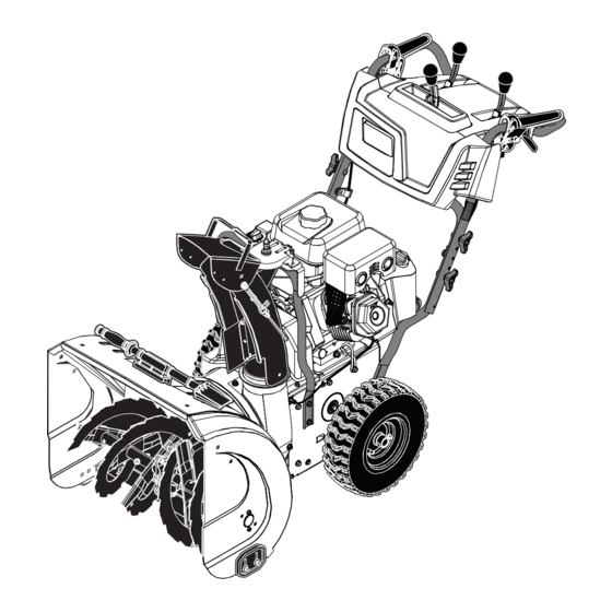
1150 SERIES B&S ENGINE
27" TWO-STAGE
POWER-PROPELLED
SNOW THROWER
• Assembly
• Operation
• Maintenance
• Service and Adjustments
• Repair Parts
Sears Canada, Inc., Toronto, Ontario M5B 2B8
Advertisement
Table of Contents

Related Manuals for Sears CRAFTSMAN 1150 Series


Summary of Contents for Sears CRAFTSMAN 1150 Series
- Page 1 • Service and Adjustments • Repair Parts Gasoline containing up to 10% ethanol (E10) is acceptable for use in this machine. The use of any gasoline exceeding 10% ethanol (E10) will void the product warranty. Sears Canada, Inc., Toronto, Ontario M5B 2B8 590607101...
-
Page 2: Safety Rules
IMPORTANT Safe Operation Practices for Walk-Behind Snow Throwers This snow thrower is capable of amputating hands and feet and throwing objects. Failure to observe the following safety instructions could result in serious injury. WARNING: Snow throwers have ex- Look for this symbol to point out im- posed rotating parts, which can cause por tant safety precautions. -
Page 3: Table Of Contents
6. When cleaning, repairing or inspecting the snow thrower, 16. Never touch a hot engine or muffler. stop the engine and make certain the collector/impel- ler and all moving parts have stopped. Disconnect Clearing a Clogged Discharge Chute the spark plug wire and keep the wire away from the Hand contact with the rotating impeller inside the discharge plug to prevent someone from accidentally starting the chute is the most common cause of injury associated with... -
Page 4: Warranty
THIS PARAGRAPH SHALL NOT APPLY, BUT THE REMAINING PROVISIONS OF THIS DOCUMENT SHALL REMAIN VALID. SEARS retains the exclusive right to repair or replace the product or offer a full refund of the purchase price at its sole discretion. SUCH REMEDY SHALL BE YOUR SOLE AND EXCLUSIVE REMEDY FOR ANY BREACH OF WARRANTY. - Page 5 PARTS PACKED SEPARATELY IN CARTON (2) LOCKNUTS (2) SHEAR BOLTS 1/4-20 x 1-3/4 1/4-20 (1) POWER CORD SAFTEY IGNITION KEY (S) (3) KNOB (2) CARRIAGE BOLTS 5/16-18 x 2 1/4” (1) LOCKNUT (1) CARRIAGE BOLT (1) SPRING 5/16-18 5/16-18 x 5/8 (1) LOCKNUT (1) NYLON (1) SHOULDER...
-
Page 6: Assembly / Pre-Operation
ASSEMBLY / PRE-OPERATION Read these instructions and this manual in its entirety before you attempt to assemble or operate your new snow thrower. Reading the entire manual will familiarize you with the unit, which will assist you in assembly, operation and maintenance of the product. - Page 7 ASSEMBLY / PRE-OPERATION INSTALL DISCHARGE CHUTE / CHUTE ROTATOR HEAD INSTALL CHUTE DEFLECTOR REMOTE CONTROL (See Fig. 4 and 5) (See Figs. 6 and 7) 1. Install remote cable bracket to discharge chute with 1. Place discharge chute assembly on top of chute base 5/16-18 carriage bolt and 5/16-18 locknut as shown.
-
Page 8: Operation
OPERATION KNOW YOUR SNOW THROWER READ THIS OWNER'S MANUAL AND ALL SAFETY RULES BEFORE OPERATING YOUR SNOW THROWER. Compare the illustrations with your snow thrower to familiarize yourself with the location of various controls and adjustments. Save this manual for future reference. These symbols may appear on your snow thrower or in literature supplied with the product. - Page 9 OPERATION DISCHARGE CHUTE CONTROL LEVER GAS O LINE AUGER FILLER CAP CONTROL DRIVE SPEED ELECTRIC LEVER CON TROL LEVER START MUF FLER BUTTON RECOIL DEFLECTOR STARTER REMOTE HANDLE CONTROL CHOKE LEVER CON TROL ON / OFF SWITCH PRIM ER LIGHT SAFETY IGNITION TRACTION...
- Page 10 OPERATION The operation of any snow thrower can result TO CONTROL SNOW DISCHARGE (See Fig. 11) in foreign objects thrown into the eyes, which WARNING: Snow throwers have ex- can result in severe eye damage. Always wear posed rotating parts, which can cause safety glasses or eye shields while operating severe injury from contact, or from ma- your snow thrower or performing any ad just-...
- Page 11 OPERATION USING THE CLEAN-OUT TOOL (See Fig. 13) CAUTION: Do not move speed con trol le ver In certain snow conditions, the discharge chute may when traction drive control lever is en gaged. become clogged with ice and snow. Use the clean-out tool Damage to the snow thrower can result.
- Page 12 OPERATION BEFORE STARTING THE ENGINE TO ADJUST SKID PLATES (See Fig. 16) NOTE: The wrench provided in your parts bag may be CHECK ENGINE OIL LEVEL (See Fig. 17) used to adjust the skid plates. The engine on your snow thrower has been shipped from Skid plates are located on each side of the auger housing the factory already filled with oil.
- Page 13 OPERATION TO START ENGINE 6. Pull recoil starter handle quickly. Do not allow starter rope to snap back. Your snow thrower engine is equipped with both a 120 Volt A.C. electric starter and a recoil starter. The electric starter 7. When the engine starts, release the recoil starter is equipped with a three-wire power plug and is designed han dle and slowly move the choke control to the “OFF”...
-
Page 14: Maintenance Schedule
MAINTENANCE LUBRICATION CHART GENERAL REC OM MEN DA TIONS ➀ The warranty on this snow thrower does not cover items SAE 5w30 Motor Oil that have been sub ject ed to operator abuse or negligence. ➁ See “Engine” in Maintenance section To receive full value from the warranty, operator must ➂... - Page 15 MAINTENANCE SNOW THROWER Check the crankcase oil level before starting the engine and after each five (5) hours of continuous use. Tighten oil Always observe the safety rules when performing any fill cap / dipstick securely each time you check the oil level. main te nance.
-
Page 16: Service And Adjustments
SERVICE AND ADJUSTMENTS To replace the shear bolts: WARNING: To avoid serious injury, before 1. Disengage all controls and move throttle control to performing any service or ad just ments: STOP position. Wait for all moving parts to stop. 1. Be sure the on/off switch is in the 2. - Page 17 SERVICE AND ADJUSTMENTS TO REPLACE BELTS AUGER BELT REPLACEMENT (See Fig. 21) TO REMOVE AUGER BELT The auger and traction drive belts are not adjustable. If the belts are damaged or begin to slip from wear, they should 1. Remove upper 5/16” bolts and lower 1/4” bolts from be replaced.
- Page 18 SERVICE AND ADJUSTMENTS AFTER REPLACING BELT(S) DRIVE BELT REPLACEMENT (See Fig. 22) 1. INSTALL BELT COVER and two (2) screws. Tighten TO REMOVE DRIVE BELT securely. 1. Remove auger belt. See “TO REMOVE AUGER BELT” 2. INSTALL DISCHARGE CHUTE – See “INSTALL in this section.
-
Page 19: Storage
STORAGE Immediately prepare your snow thrower for storage at • Empty the fuel tank by starting the engine and letting it run until the fuel lines and car bu re tor are empty. the end of the season or if the unit will not be used for 30 days or more. -
Page 20: Troubleshooting
TROUBLESHOOTING See appropriate section in manual unless directed to a Sears service center/department. PROBLEM CAUSE CORRECTION Does not start 1. Fuel shut-off valve (if so equipped) 1. Turn fuel shut-off valve to OPEN position. in OFF position. 2. Safety ignition key is not inserted. - Page 21 SERVICE NOTES...
-
Page 22: Repair Parts
SNOW THROWER - - MODEL NUMBER 944.103252 REPAIR PARTS AUGER HOUSING / IMPELLER ASSEMBLY 05.09.009-J NOTE: All component dimensions given in U.S. inches. 1 inch = 25.4 mm IMPORTANT: Use only Original Equipment Manufacturer (O.E.M.) replacement parts. Failure to do so could be hazardous, damage your snow thrower and void your warranty. - Page 23 SNOW THROWER - - MODEL NUMBER 944.103252 REPAIR PARTS AUGER HOUSING / IMPELLER ASSEMBLY PART DESCRIPTION 501149601 GEARBOX AUGER 586607202 IMPELLER STEEL 587402401 PULLEY IMPELLER – SCREW ON 585056901 CHUTE DISCHARGE BASE 178675X008 BRACKET CORNER DISCHARGE BASE 588077501 BOLT SHEAR 1/4-20 73800400 NUT NYLOCK 1/4-20 585691301...
- Page 24 SNOW THROWER - - MODEL NUMBER 944.103252 REPAIR PARTS AUGER HOUSING / IMPELLER ASSEMBLY PART DESCRIPTION 581708373 AUGER HOUSING 404932X428 SCRAPER BAR 72270505 CARRIAGE BOLT 5/16-18 X .625 GR5 155377 NUT 5/16-18 05.09.011-D PART DESCRIPTION 420495X 479 AUGER 27 LH 420496X479 AUGER 27 RH 05.09.006-C...
- Page 25 SNOW THROWER - - MODEL NUMBER 944.103252 REPAIR PARTS AUGER HOUSING / IMPELLER ASSEMBLY PART DESCRIPTION 420478 AUGER BEARING 411939 BEARING PLUG 584299401 SCREW HI-LO WASHD 5/16-14 X 1.00 05.09.007-A PART DESCRIPTION 192199 TOOL CLEANOUT 405400 CLIP CLEANOUT TOOL 194189 SCREW HEX WASHER 13-16 X 5/8 05.09.039-A...
- Page 26 SNOW THROWER - - MODEL NUMBER 944.103252 REPAIR PARTS CONTROL PANEL / DISCHARGE CHUTE PART DESCRIPTION 581131203 CONSOLE BASE MULTICONT W/SWITCH 585805001 SWITCH GRIP HEATED BLACK 17060410 SCREW TA SEMI GIMLE 1/4- 20 X .62 581329501 SCREW HEX WASHER 13-16 X 1.50 05.07.009-A PART...
- Page 27 SNOW THROWER - - MODEL NUMBER 944.103252 REPAIR PARTS CONTROL PANEL / DISCHARGE CHUTE PART DESCRIPTION 588263901 CABLE, POWER STEER - LHS 588263902 CABLE, POWER STEER - RHS 587463001 LEVER, CONTROL 587739701 LEVER, CABLE ARM - LHS 587739702 LEVER, CABLE ARM - RHS 581329501 SCREW HI-LO 13-16 X 1.50 17060410...
- Page 28 SNOW THROWER - - MODEL NUMBER 944.103252 REPAIR PARTS CONTROL PANEL / DISCHARGE CHUTE PART DESCRIPTION 587332502 CABLE INTERLOCK 431762 PIN GROOVED 12000014 E-RING 581151201 SPRING RETURN 197991 CLIP CABLE BLACK 05.08.001-C PART DESCRIPTION 587535701 HARNESS WIRE LIGHTS & GRIPS 145006 WIRE RETAINER 05.19.002-A...
- Page 29 SNOW THROWER - - MODEL NUMBER 944.103252 REPAIR PARTS CONTROL PANEL / DISCHARGE CHUTE 05.08.011-C PART DESCRIPTION 582519001 CABLE CONTROL DRIVE 588113801 CABLE CONTROL AUGER 588122301 CABLE CONTROL SPEED 197991 CLIP CABLE 428124 FASTENER PUSH .250 581329401 PIN CLEVIS 5/16 423303 HAIRPIN 585808301...
- Page 30 SNOW THROWER - - MODEL NUMBER 944.103252 REPAIR PARTS CONTROL PANEL / DISCHARGE CHUTE 05.08.010-A PART DESCRIPTION 587803401 CABLE CHUTE ROTATOR ASM 581329401 PIN CLEVIS 5/6 X 7/8 77100812 PIN CLEVIS 1/4 X 3/4 423303 HAIRPIN SOFT ZINC 584652201 CLIP CONDUIT DOUBLE 586682101 WASHER 587130801...
- Page 31 SNOW THROWER - - MODEL NUMBER 944.103252 REPAIR PARTS CONTROL PANEL / DISCHARGE CHUTE PART DESCRIPTION 588077803 CHUTE WELDMENT ASM. (INCLUDES 1-6) – – – – – – RIVETED DEFLECTOR ASM. – – – – – – DEFLECTOR SEAL – – – – – – POP RIVET –...
- Page 32 SNOW THROWER - - MODEL NUMBER 944.103252 REPAIR PARTS HANDLES PART DESCRIPTION 588160802 UPPER HANDLE 189713X428 HANDLE KNOB STD BLACK 588059901 SCREW 5/16-18 X 2.25 CONCAVE HEAD WITH PATCH 05.06.001-G PART DESCRIPTION 588672102 LOWER HANDLE 17000612 SCREW HEX WASH HD 3/8-16 X .75 581622002 CHUTE ROTATOR SUPPORT...
- Page 33 SNOW THROWER - - MODEL NUMBER 944.103252 REPAIR PARTS DRIVE 05.03.002-B PART DESCRIPTION 444949 WASHER 1.00 587978901 BUSHING HEX 1 SHAFT 588518601 GEAR 59T DRIVEN 12000053 RETAINING RING 580752601 AXLE SHAFT SPLIT 4497H RETAINER SPRING 1 ZINC 126875X RIVET RD HD DRILLED 1/4 DIA 580752501 AXLE SLEEVE NOTE: All component dimensions given in U.S.
- Page 34 SNOW THROWER - - MODEL NUMBER 944.103252 REPAIR PARTS DRIVE 05.02.002-G NOTE: All component dimensions given in U.S. inches. 1 inch = 25.4 mm IMPORTANT: Use only Original Equipment Manufacturer (O.E.M.) replacement parts. Failure to do so could be hazardous, damage your snow thrower and void your warranty.
- Page 35 SNOW THROWER - - MODEL NUMBER 944.103252 REPAIR PARTS DRIVE PART DESCRIPTION 521991101 NUT HEX FLANGE LK 1/2-13 587703402 SWING PLATE FRICTION PULL 581123001 ROD TIP PLATE 581732701 SPACER DRIVE 193885 LATCH SPRING 12000007 E-RING RETAINER 581328401 FRICTION DISC COMBO PULLEY 587193403 BRACKET YOKE ASSEMBLY 581315301...
- Page 36 SNOW THROWER - - MODEL NUMBER 944.103252 REPAIR PARTS CHASSIS / ENGINE / PULLEYS PART DESCRIPTION - - - - - - - - B&S ENGINE 15C107-0040-F8 580839403 FRAME 150406 ENGINE BOLT 3/8-16 X 1.280 05.01.001-H DOGPOINT 580839503 FRAME COVER 501060403 SHIFTER BRACKET 582906901...
- Page 37 SNOW THROWER - - MODEL NUMBER 944.103252 REPAIR PARTS CHASSIS / ENGINE / PULLEYS 05.04.001-K PART PART DESCRIPTION DESCRIPTION 588492802 BELT KEEPER BRACKET 581413801 SHOULDER BOLT 5/16-24 X 19111216 WASHER 11/32 X 3/4 X 16 GA 2.15 10040500 LOCKWASHER 5/16 SPLIT HVY 587893703 PULLEY ASM ENGINE 74610512...
- Page 38 SNOW THROWER - - MODEL NUMBER 944.103252 REPAIR PARTS CHASSIS / ENGINE / PULLEYS PART DESCRIPTION 587105401 BELT COVER BLACK ASSEMBLY (INCLUDES 2 & 4) - - - - - - - - - BOLT HEX WSH THDRL 1/4-20 145006 CABLE GUIDE - - - - - - - - - PALNUT 1/4 IN...
- Page 39 SNOW THROWER - - MODEL NUMBER 944.103252 REPAIR PARTS WHEELS PART DESCRIPTION 586710403 WHEEL 15 X 5.00 NPS LH 1.00 586710303 WHEEL 15 X 5.00 NPS RH 1.00 05.15.003-C NOTE: All component dimensions given in U.S. inches. 1 inch = 25.4 mm IMPORTANT: Use only Original Equipment Manufacturer (O.E.M.) replacement parts.
- Page 40 SNOW THROWER - - MODEL NUMBER 944.103252 REPAIR PARTS BAG OF PARTS PART DESCRIPTION 588077501 BOLT 1/4-20 X 1.81 73800400 NUT NYLOCK 1/4-20 501417301 BOLT SHOULDER 585691401 NUT HEX FL 1/4-20 CTR 588252901 NUT NYLOCK 3/8-16 588059901 BOLT 5/16-18 X 2.25 CONCAVE 189713X428 KNOB 5/16-18 X .625 585832001...
- Page 41 SNOW THROWER - - MODEL NUMBER 944.103252 REPAIR PARTS DECALS PART DESCRIPTION 184045 DECAL AUGER 590812201 DECAL CHUTE 199683 DECAL AUGER SAFETY 184028 DECAL BELT GUIDE 05.16.001-A NOTE: All component dimensions given in U.S. inches. 1 inch = 25.4 mm IMPORTANT: Use only Original Equipment Manufacturer (O.E.M.) replacement parts.
- Page 42 SNOW THROWER - - MODEL NUMBER 944.103252 REPAIR PARTS DECALS KEY PART DESCRIPTION 199683 DECAL, DANGER 590812201 DECAL, DANGER, DEFLECTOR 184045 DECAL, DANGER 184028 DECAL, BELT GUARD 581152801 DECAL, AUGER HOUSING BRANDED 590607101 OWNER’S MANUAL, ENGLISH 590607102 OWNER’S MANUAL, FRENCH NOTE: All component dimensions given in U.S.
-
Page 43: Engine Breakdown
SNOW THROWER - - MODEL NUMBER 944.103252 REPAIR PARTS ENGINE, B&S MODEL NUMBER 15C107-0040-F8 1036 1058 1329 1330 883A 163A 1022 1095 209A 1022 1119 1029 1034 914A 1022... - Page 44 SNOW THROWER - - MODEL NUMBER 944.103252 REPAIR PARTS ENGINE, B&S MODEL NUMBER 15C107-0040-F8 914A 1147 1023 1022 731A 957A 1230 1026 663A 1196A 1054 1196 1005 1251 1070 1251A 1252 1252A...
- Page 45 SNOW THROWER - - MODEL NUMBER 944.103252 REPAIR PARTS ENGINE, B&S MODEL NUMBER 15C107-0040-F8 307A 1427 PART PART DESCRIPTION DESCRIPTION 794188 CYLINDER ASSEMBLY 791784 SCREW (CONNECTING ROD) 299819S SEAL-OIL (MAGNETO SIDE) 499642 VALVE-EXHAUST 594701 HEAD-CYLINDER 795443 VALVE-INTAKE 698210 GASKET-CYLINDER HEAD 691304 SPRING-VALVE (INTAKE) 791716...
- Page 46 SNOW THROWER - - MODEL NUMBER 944.103252 REPAIR PARTS ENGINE, B&S MODEL NUMBER 15C107-0040-F8 PART PART DESCRIPTION DESCRIPTION 797634 KIT-CARBURETOR 695383 WASHER SET-FRICTION OVERHAUL (CONTROL BRACKET) 791717 SPACER-CARBURETOR 691251 NUT (GOVERNOR CONTROL 594015 CARBURETOR LEVER) 797633 PLUG-WELCH 798469 DIPSTICK 797630 VALVE-THROTTLE 281370S SEAL-O RING (DIPSTICK...
- Page 47 SNOW THROWER - - MODEL NUMBER 944.103252 REPAIR PARTS ENGINE, B&S MODEL NUMBER 15C107-0040-F8 PART PART DESCRIPTION DESCRIPTION 594230 STUD-ROCKER ARM 1054 280275 TIE-CABLE 793193 GUARD-MUFFLER 1058 OPERATOR’S MANUAL 699854 SCREW (MUFFLER GUARD) (NOT AVAILABLE AT THIS 795015 SEAL-O RING (DIPSTICK) PRINTING) 798468 DIPSTICK/TUBE ASSEMBLY...
- Page 48 04.27.17 BD Printed in the U.S.A.
Need help?
Do you have a question about the CRAFTSMAN 1150 Series and is the answer not in the manual?
Questions and answers