Table of Contents
Advertisement
Quick Links
OWNER'S
MANUAL
MODEL NO.
C 151 61576 0
C 151 61577 0
Caution:
Read and Follow
All Safety Rules
and Instructions
Before Operating
This Equipment
Sears Canada, Inc., Toronto, Ontario M5B 2B8
104158
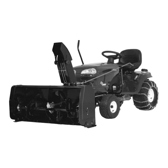
44" AND 48" NORTHEAST TWO
STAGE SNOWBLOWER FOR
CRAFTSMAN TRACTORS
·Assembly
·Operation
·Maintenance
·Repair Parts
1
F-07
Advertisement
Table of Contents

Subscribe to Our Youtube Channel
Related Manuals for Sears CRAFTSMAN C 151 61576 0


Summary of Contents for Sears CRAFTSMAN C 151 61576 0
- Page 1 C 151 61577 0 44" AND 48" NORTHEAST TWO STAGE SNOWBLOWER FOR Caution: CRAFTSMAN TRACTORS Read and Follow All Safety Rules and Instructions ·Assembly Before Operating ·Operation This Equipment ·Maintenance ·Repair Parts Sears Canada, Inc., Toronto, Ontario M5B 2B8 104158 F-07...
- Page 2 LIMITED ONE (1) YEAR WARRANTY ON CRAFTSMAN TRACTOR ATTACHMENTS "SNOWBLOWER" For one (1) year from date of purchase, Sears Canada Inc. will repair or replace free of charge at Sears option any parts which are defective as a result of defective material or faulty workmanship.
-
Page 3: Table Of Contents
TABLE OF CONTENTS Page INTRODUCTION ............................SAFETY PRECAUTIONS ......................... SAFETY DECALS ............................. ASSEMBLY Step 1: Tractor Preparation ......................Step 2: Subframe Installation ....................... Step 3: Drive Mechanism Preparation ..................Step 4: Drive Mechanism Installation ................... Step 5: Snowblower Preparation ....................Step 6: Snowblower Installation .................... -
Page 4: Introduction
INTRODUCTION TO THE PURCHASER This new attachment was carefully designed to give years of dependable service. This manual has been provided to assist in the safe operation and servicing of your attachment. NOTE: All photographs and illustrations in the manual may not necessarily depict the actual models or attachment, but are intended for reference only and are based on the latest product information available at the time of publication. -
Page 5: Safety Precautions
SAFETY PRECAUTIONS Careful operation is your best insurance against an accident. Read this section carefully before operating the tractor and snowblower. This snowblower is capable of amputating hands and feet and throwing objects. Failure to observe the following safety instructions could result in serious injury. All operators, no matter how experienced they may be, should read this and other manuals related to the tractor and snowblower before operating. - Page 6 SAFETY PRECAUTIONS 4. If the unit should start to vibrate abnormally, stop 16. Use only accessories approved the engine (motor) and check immediately for the manufacturer of the snowblower (such as wheel cause. Vibration is generally a warning of trouble. chains, counterweights, cabs).
-
Page 7: Safety Decals
SAFETY DECALS REPLACE IF DECALS ARE DAMAGED SEE PARTS BREAKDOWN FOR DECAL LOCATION Decal # 102124 Decal # 102125 Decal # 102126 Decal # 102127 Decal # 102128 Decal # 103951... -
Page 8: Assembly
ASSEMBLY IMPORTANT: TORQUE ALL BOLTS ACCORDING TO TORQUE SPECIFICATION TABLE (SEE TABLE CONTENTS) WHEN STATED: TIGHTEN FIRMLY. REFER PARTS BREAKDOWN SECTION FOR PARTS IDENTIFICATION. NOTE: This subframe was designed to fit various models of Lawn, Yard or Garden tractors. (See illustrations to identify your tractor). -
Page 9: Step 2: Subframe Installation
ASSEMBLY STEP 2 SUBFRAME INSTALLATION: FOR LAWN & YARD TRACTORS: Install a hex. nut 1/2" (item 1) on each end of the brace pin (item 2) (halfway down the threads). Install the longest end (item 2) of the brace pin in the top nut (item 4) welded on the right support. - Page 10 ASSEMBLY FOR LAWN & YARD TRACTORS: Install the left support (item 1) by inserting the top Figure A hole (item 3) on the brace pin (item 2) as shown in figure A. Hold in place with three thread cutting screws 3/8 x 1"...
- Page 11 ASSEMBLY FOR GARDEN TRACTORS: Install the left support (item 1) by inserting it on the Figure A brace pin (item 2) as shown in figure A. 3 possible positions for the brace pin Hold in place with two thread cutting screws 3/8 x 1"...
- Page 12 ASSEMBLY ASSEMBLY FOR LAWN, YARD AND GARDEN TRACTORS: Turn the front wheels towards the left. Install the pivot support (item 1) between the two supports and slide in place the pin (item 2) in the top hole for Lawn & Yard tractors or the bottom hole for Garden tractors.
-
Page 13: Step 3: Drive Mechanism Preparation
ASSEMBLY VERY IMPORTANT ADJUST LIFT HEIGHT ACCESSORIES ON LAWN,YARD AND GARDEN TRACTORS. This adjustment is necessary in order to allow the accessories to follow the contours of the ground and to avoid damage to the accessories. The link (item 1) has an adjustment bolt (item 2) to adjust the height of the accessories: Compact Snowblower: max. - Page 14 ASSEMBLY NOTE: This drive mechanism may be mounted on NOTE: The drive mechanism must be straight, to tractors with two types of clutch mechanisms. See the make sure the belt works well. following instructions for those that are appropriate for your tractor.
-
Page 15: Step 4: Drive Mechanism Installation
ASSEMBLY STEP 4 DRIVE MECHANISM INSTALLATION: Install the drive mechanism according to the appropriate figure for you tractor. Install the drive mechanism (item 1) by hooking the front part of the drive frame (item 2) on the brace pin (item 3). Lift and attach the rear portion of the drive frame between the supports (items 4 &... -
Page 16: Step 5: Snowblower Preparation
ASSEMBLY STEP 5 SNOWBLOWER PREPARATION: Install the hand guard (item 1) in the chute (item 2) as shown. Secure in place with two 1/4 x 3/4" hex bolts, two flat washers and two 1/4’’ flange nuts on the inside. Tighten firmly. Install hand guard Before installing the chute (item 1), loosen the two flange nuts (item 2) (down to the last threads) which... -
Page 17: Step 6: Snowblower Installation
ASSEMBLY STEP 6 SNOWBLOWER INSTALLATION: Refer parts breakdown section parts identification. WARNING TO PREVENT INJURIES: Stop the motor. Apply parking brake. Remove the ignition key. Disconnect the wire from the spark plug(s) and keep away from spark plug(s) to prevent accidental starting. - Page 18 ASSEMBLY VERIFY BELT ROUTING: -Lower the snowblower to the ground and let it run for a few seconds under supervision. -Disengage the snowblower and stop the engine. -Remove the belt guard. -Check the belts to make sure they are well inserted in the pulleys and that they have not flipped on their sides on the pulleys and that they do not touch the belt guides.
-
Page 19: Operation
OPERATION SNOWBLOWER OPERATION WARNING a) Make sure the snowblower is clear of snow -Do not attempt to clear plugged chute, auger or before engaging the snowblower. fan of snow while tractor engine is running. -Disengage snowblower. b) Make sure that the auger and impeller operate -Lower snowblower onto ground. -
Page 20: Maintenance
MAINTENANCE CUTTING EDGE MAINTENANCE WARNING Verify from time to time the wearing on the cutting TO PREVENT INJURIES: edge to make sure you do not wear out the base of the snowblower’s chassis. This cutting edge is Stop the motor. reversible. -
Page 21: Belt Installation, Adjustment And Replacement
MAINTENANCE BELT INSTALLATION, ADJUSTMENT, AND REPLACEMENT: Snowblower Belt: Snowblower pulley a) Lower the snowblower to the ground. b) Install the belt as shown in the diagram. c) Apply tension to the belt by pulling up the tension arm. d) Engage the snowblower for a few seconds under supervision. -
Page 22: Dismounting
DISMOUNTING SNOWBLOWER DISMOUNTING DRIVE MECHANISM DISMOUNTING a) Dismount the attachment. WARNING b) Remove the rear counterweight when you remove the front attachment. TO PREVENT INJURIES: Stop the motor. c) Dismount the drive mechanism by supporting it in Apply parking brakes. hand and removing the two hair pins and the pins. -
Page 23: Troubleshooting
TROUBLESHOOTING PROBLEM POSSIBLE CAUSES CORRECTIVE ACTION One section or both sections of the Shear bolts are probably broken. R e p l a c e s h e a r b o l t ( f o r auger stops turning. identification, parts list... - Page 24 TROUBLESHOOTING PROBLEM POSSIBLE CAUSES CORRECTIVE ACTION Snowblower digs into ground. Ground is not frozen or too soft. Adjust skid shoes lower so they may better support the snowblower. If problem persists, change skid shoes for heavy duty skid shoes (option #700243) which cover more surface and prevents snowblower from digging.
-
Page 25: Torque Specification Table
TORQUE SPECIFICATION TABLE GENERAL TORQUE SPECIFICATION TABLE USE THE FOLLOWING TORQUES WHEN SPECIAL TORQUES ARE NOT GIVEN NOTE: These values apply to fasteners as received from supplier, dry or when lubricated with normal oil. They do not apply if special graphited or moly disulphide greases or other extreme pressure lubricants are used. This applies to both UNF and UNC threads. -
Page 26: Drive Mechanism
PARTS BREAKDOWN / NOMENCLATURE DES PIÈCES NORTHEAST DRIVE MECHANISM MÉCANISME D’ENTRAINEMENT NORDET... - Page 27 PARTS LIST / LISTE DES PIÈCES Ref. Qty. Part # English description Description française Réf. Qté. Pièce # 1 Drive frame Châssis d'entraînement 104097 2 Idler arm Bras de tension 104096 3 Cable holder Fixation du câble 104092 4 Support Support 104098 5 Support...
-
Page 28: Subframe
PARTS BREAKDOWN / NOMENCLATURE DES PIÈCES SUBFRAME / SOUS-CHÂSSIS... - Page 29 PARTS LIST / LISTE DES PIÈCES Ref. English description Description française Qty. Part # Réf. Qté. Pièce # 1 Right support Support droit 104081 2 Lift arm Bras de relevage 104083 3 Left support Support gauche 104082 4 Brace pin Tige de renfort 104086 5 Lever...
- Page 30 PARTS LIST / LISTE DES PIÈCES Ref. English description Description française Qty. Part # Réf. Qté. Pièce # 39 Washer Rondelle 104113 40 Washer Rondelle 104125 41 Carriage bolt 3/8" n.c. x 1 1/4" Boulon à carrosserie 3/8" n.c. x 1 1/4" STD533712 O/L = Obtain locally/obtenir localement...
-
Page 31: Chute With Rotation System
PARTS BREAKDOWN / NOMENCLATURE DES PIÈCES CHUTE WITH ROTATION SYSTEM / GOULOTTE AVEC SYSTÈME DE ROTATION... - Page 32 PARTS LIST / LISTE DES PIÈCES REF. DESCRIPTION DESCRIPTION PART # RÉF. QTÉ PIÈCE # 1 Chute Goulotte 103936 2 Rotation bushing Coussinet de rotation 103945 3 Rotation worm Spirale de rotation 102005 4 Worm support Support spirale 103941 5 Worm support Support spirale 103942 6 Rotation ring...
-
Page 33: Snowblower
PARTS BREAKDOWN / NOMENCLATURE DES PIÈCES SNOWBLOWER / SOUFFLEUSE... - Page 34 PARTS LIST / LISTE DES PIÈCES REF. PART # DESCRIPTION DESCRIPTION RÉF. QTÉ PIÈCE # 1 Frame 44" Châssis 44" 103929 2 Frame 48" Châssis 48" 103954 3 Shear plate Plaque de cisaillement 103933 4 Fan Éventail 103932 5 Flangette Flangette 102213 6 Bearing with set screw...
- Page 35 PARTS LIST / LISTE DES PIÈCES REF. PART # DESCRIPTION DESCRIPTION RÉF. QTÉ PIÈCE # 36 Carriage bolt 3/8" n.c. x 1 1/4" Boulon à carrosserie 3/8" n.c. x 1 1/4" STD533712 37 Tension arm Bras de tension 103026 38 Handgrip Poignée 102062 39 Carriage bolt 3/8"...
-
Page 36: Options & Attachments
ATTACHMENTS & OPTIONS ROTARY BROOM #700381 with polypropylene brush. COUNTERWEIGHT UTILITY BLADE #61913 Fits on same subframe as #700266 Required for safety and traction. snowblower & utility blade Mounts on the same subframe as the Counter-balances weight of Requires adaptor #700379 snowblower &... -
Page 37: Consumer Information
_______________________________________________________________________________________________ Pour service en francais: 1-800-LE-FOYER (1-800-533-6937) www.sears.ca ®/TM Trademarks of Sears, Roebuck and Co. used under license by Sears Canada ® Marque deposée/ Marque de commerce de Sears, Roebuck and Co. utilisée en vertu d’une licence de Sears Canada...
Need help?
Do you have a question about the CRAFTSMAN C 151 61576 0 and is the answer not in the manual?
Questions and answers
Need to replace the ****
The replacement parts for the Sears CRAFTSMAN C 151 61576 0 Snow Blower include:
- Carriage bolt 3/8" n.c. x 1 1/4" (Part # STD533712)
- Tension arm (Part # 103026)
- Handgrip (Part # 102062)
- Carriage bolt 3/8" n.c. x 1-1/2" (Part # STD533715)
- Sleeve (Part # 103028)
- Flange washer (Part # 103481)
- Tension arm (Part # 103947)
- V pulley (Part # 103740)
- Spring (Part # 102861)
- Belt guard (Part # 103937)
- Knob (Part # 103027)
- Gearbox support (Part # 103940)
- Flat washer 3/8" hole (Part # STD551037)
- Hex bolt 5/16" n.c. x 3/4" (Part # STD523107)
- Roll pin 3/8" x 3/4"
These parts are listed in the manual as components of the snow blower.
This answer is automatically generated