Table of Contents
Advertisement
Quick Links
OWNER'S
MANUAL
MODEL NO.
944.529933
Caution:
Read and fol low
all Safety Rules
and In struc tions
Be fore Op er at ing
This Equip ment
Sears Canada, Inc., Toronto, Ontario M5B 2B8
1450 SERIES B&S ENGINE
27" TWO-STAGE
POWER-PROPELLED
SNOW THROWER
• Assembly
• Operation
• Maintenance
• Service and Adjustments
• Repair Parts
Advertisement
Table of Contents

Related Manuals for Sears 944.529933


Summary of Contents for Sears 944.529933
- Page 1 27" TWO-STAGE all Safety Rules POWER-PROPELLED and In struc tions Be fore Op er at ing SNOW THROWER This Equip ment • Assembly • Operation • Maintenance • Service and Adjustments • Repair Parts Sears Canada, Inc., Toronto, Ontario M5B 2B8...
-
Page 2: Safety Rules
IMPORTANT Safe Operation Practices for Walk-Behind Snow Throwers This snow thrower is capable of amputating hands and feet and throwing objects. Failure to observe the following safety instructions could result in serious injury. WARNING: Snow throwers have ex- Look for this symbol to point out im- posed rotating parts, which can cause por tant safety precautions. -
Page 3: Table Of Contents
Clearing a Clogged Discharge Chute 6. When cleaning, repairing or inspecting the snow thrower, stop the engine and make certain the collector/impel- Hand contact with the rotating impeller inside the discharge ler and all moving parts have stopped. Disconnect chute is the most common cause of injury associated with the spark plug wire and keep the wire away from the snow throwers. -
Page 4: Warranty
THIS PARAGRAPH SHALL NOT APPLY, BUT THE REMAINING PROVISIONS OF THIS DOCUMENT SHALL REMAIN VALID. SEARS retains the exclusive right to repair or replace the product or offer a full refund of the purchase price at its sole discretion. SUCH REMEDY SHALL BE YOUR SOLE AND EXCLUSIVE REMEDY FOR ANY BREACH OF WARRANTY. -
Page 5: Assembly / Pre-Operation
PARTS PACKED SEPARATELY IN CARTON (1) MULTI- (1) FUEL STABILIZER PACKET WRENCH (180684) (1) POWER CORD SAFTEY IGNITION KEY(S) (193071) (198563) (1) AUGER CONTROL ROD (2) FLAT WASHERS (1) DISCHARGE CHUTE EXTRA SHEAR BOLTS AND NUTS (2) SHOULDER (2) LOCKNUTS (2) CARRIAGE BOLTS BOLT 1/4-20 x 1-3/4 1/4-20... - Page 6 ASSEMBLY / PRE-OPERATION NOTE: The multi-wrench may be used for assembly of the INSTALL TRACTION DRIVE CONTROL ROD chute rotator head to snow thrower and making ad just ments (See Figs. 3 and 4) to the skid plates. The traction drive control rod is installed on the snow thrower.
- Page 7 ASSEMBLY / PRE-OPERATION INSTALL AUGER CONTROL ROD (See Figs. 5 and 6) INSTALL DISCHARGE CHUTE / CHUTE ROTATOR 1. Retrieve vinyl sleeve and spring from bag of parts and HEAD (See Fig. 7) retrieve the auger control rod from carton chute tray. NOTE: The multi-wrench provided in your parts bag may Slide straight rod end through the small hole in the be used to install the chute rotator head.
- Page 8 ASSEMBLY / PRE-OPERATION INSTALL CHUTE DEFLECTOR REMOTE CONTROL (See Figs. 8 and 9) 1. Install remote cable bracket to discharge chute with 5/16-18 carriage bolt and 5/16-18 locknut as shown. Tighten securely. 2. Install remote cable eyelet to chute deflector with 1/4-20 shoulder bolt and 1/4-20 locknut as shown.
-
Page 9: Operation
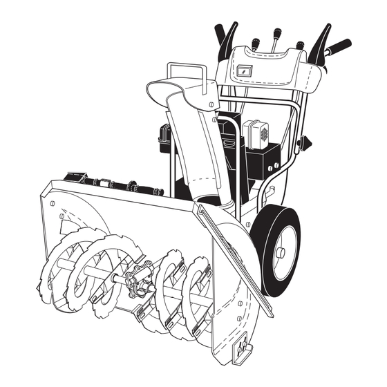
OPERATION KNOW YOUR SNOW THROWER READ THIS OWNER'S MANUAL AND ALL SAFETY RULES BEFORE OPERATING YOUR SNOW THROWER. Compare the illustrations with your snow thrower to familiarize yourself with the location of various controls and adjustments. Save this manual for future reference. These symbols may appear on your snow thrower or in literature supplied with the product. - Page 10 OPERATION TRACTION AUGER DRIVE DISCHARGE DEFLECTOR GAS O LINE ELECTRIC DRIVE CONTROL SPEED CHUTE REMOTE FILLER CAP START CONTROL CONTROL CONTROL LEVER CON TROL BUTTON LEVER LEVER LEVER LEVER MUF FLER RECOIL (AUXILIARY) STARTER HANDLE CHUTE CHOKE DE FLEC TOR CON- TROL PRIM ER...
- Page 11 OPERATION The operation of any snow thrower can result TO CONTROL SNOW DISCHARGE (See Fig. 13) in foreign objects thrown into the eyes, which can result in severe eye damage. Always wear WARNING: Snow throwers have ex- safety glasses or eye shields while operating posed rotating parts, which can cause your snow thrower or performing any ad just - severe injury from contact, or from ma-...
- Page 12 OPERATION TO THROW SNOW (See Fig. 14) The auger rotation is controlled by the auger control lever DISCHARGE CHUTE located on the right side handle. • Squeeze auger control lever to handle to engage the auger and throw snow. • Release the auger control lever to stop throwing snow.
- Page 13 OPERATION POWER STEERING OPERATION (See Fig. 17) HIGH POSITION Steering triggers are used to assist in steering your snow (LOW GROUND thrower. The triggers are located on the underside of each CLEARANCE) handle. When a trigger is squeezed, it disengages the AUGER drive wheel on that side of snow thrower and allows it to HOUSING...
- Page 14 OPERATION BEFORE STARTING THE ENGINE TO START ENGINE Your snow thrower engine is equipped with both a 120 Volt CHECK ENGINE OIL LEVEL (See Fig. 21) A.C. electric starter and a recoil starter. The electric starter The engine on your snow thrower has been shipped, from is equipped with a three-wire power cord and plug and is the factory, already filled with oil.
- Page 15 OPERATION SNOW THROWING TIPS NOTE: Over priming may cause flooding, preventing the • Always operate the snow thrower with the engine at engine from starting. If you do flood the engine, wait a full throttle. Full throttle offers the best performance. few minutes be fore at tempt ing to start and DO NOT push •...
-
Page 16: Maintenance Schedule
MAINTENANCE GENERAL REC OM MEN DA TIONS LUBRICATION CHART The warranty on this snow thrower does not cover items that have been sub ject ed to operator abuse or negligence. SAE 5W-30 Motor Oil To receive full value from the warranty, operator must maintain snow thrower as in struct ed in this manual. - Page 17 MAINTENANCE AUGER GEAR CASE NOTE: The left side wheel may be removed from snow thrower for easier access to the oil drain plug and place- • The gear case was filled with lubricant to the proper ment of a suitable container. The unit tilted, resting on the level at the factory.
-
Page 18: Service And Adjustments
SERVICE AND ADJUSTMENTS WARNING: To avoid serious injury, before performing any service or ad just ments: 1. Be sure throttle is in STOP position. 2. Remove safety ignition key. 3. Make sure the augers and all mov ing parts have completely stopped. 4. - Page 19 (OEM) belts avail able from your nearest Sears service center/department. Using other than OEM belts can cause 10. While your assistant slowly raises handles to rejoin personal injury or damage to the snow thrower.
- Page 20 If you think the engine-governed high speed needs adjusting, contact a Sears or other qualified service center, which has proper equipment and experience to make any necessary ad just ments.
-
Page 21: Storage
STORAGE Immediately prepare your unit for storage at the end of the FUEL SYS TEM season or if the unit will not be used for 30 days or more. IMPORTANT: It is important to prevent gum deposits from forming in essential fuel system parts such as carburetor, WARNING: Never store the snow fuel hose, or tank during storage. -
Page 22: Troubleshooting
TROUBLESHOOTING See appropriate section in manual unless directed to a Sears service center/department. PROBLEM CAUSE CORRECTION Does not start 1. Fuel shut-off valve (if so 1. Turn fuel shut-off valve to OPEN position. equipped) in OFF position. 2. Safety ignition key 2. -
Page 23: Repair Parts
SNOW THROWER - - MODEL NUMBER 944.529933 REPAIR PARTS AUGER HOUSING / IMPELLER ASSEMBLY 3 (5x) PART 4 (5x) DESCRIPTION 404929X615 AUGER HOUSING 27 404932X429 SCRAPER BAR 72270505 CARRIAGE BOLT 5/16−18 X .625 155377 NUT 5/16−18 01.07.002-A PART DESCRIPTION 420495X479... - Page 24 SNOW THROWER - - MODEL NUMBER 944.529933 REPAIR PARTS AUGER HOUSING / IMPELLER ASSEMBLY (EXPLODED) 01.07.026-C...
- Page 25 SNOW THROWER - - MODEL NUMBER 944.529933 REPAIR PARTS AUGER HOUSING / IMPELLER ASSEMBLY PART DESCRIPTION 175321X479 IMPELLER 427148 GEARBOX ASSEMBLY 188909 BEARING 427146 IMPELLER PULLEY 175322 DISCHARGE BASE 178675X008 CORNER BRACKET 192199 CLEAN OUT TOOL 405400 TOOL CLIP 73800400...
- Page 26 SNOW THROWER - - MODEL NUMBER 944.529933 REPAIR PARTS AUGER HOUSING / IMPELLER ASSEMBLY PART DESCRIPTION 01.11.001-A 174762X479 SKID PLATE LH 178777X479 SKID PLATE RH 72270506 CARRIAGE BOLT 5/16−18 X .75 751153 NUT 5/16−18 PART DESCRIPTION 420478 AUGER BEARING 01.07.024-B...
- Page 27 SNOW THROWER - - MODEL NUMBER 944.529933 REPAIR PARTS AUGER HOUSING / IMPELLER ASSEMBLY 01.16.001-A PART DESCRIPTION 181160X479 DRIFT CUTTER BAR 72270506 CARRIAGE BOLT 5/16−18 X .750 179246 PLASTIC WASHER 10040500 LOCKWASHER 5/16 128638 NUT 5/16−18 NOTE: All component dimensions given in U.S. inches.
- Page 28 SNOW THROWER - - MODEL NUMBER 944.529933 REPAIR PARTS CONTROL PANEL / DISCHARGE CHUTE PART DESCRIPTION 420315X615 CHUTE WELDMENT 178633X615 DEFLECTOR WELDMENT 01.09.002-D 420673 DEFLECTOR CONTROL ASSEMBLY 420325 DEFLECTOR SEAL 414280 KNOB BLACK 128415 POP RIVET 17501010 SCREW 10-24 X .625...
- Page 29 SNOW THROWER - - MODEL NUMBER 944.529933 REPAIR PARTS CONTROL PANEL / DISCHARGE CHUTE PART 01.09.010-B DESCRIPTION 428272 LEVER/CABLE ROTATOR ASSEMBLY 17501010 SCREW 10-24 X .625 420678 ROTATOR HEAD 405932 ROTATOR PIVOT BRACKET 420675 PULLEY PIVOT 428273 CABLE ASSEMBLY ADJUSTABLE...
- Page 30 SNOW THROWER - - MODEL NUMBER 944.529933 REPAIR PARTS HANDLES PART DESCRIPTION 419800X479 PLOW HANDLE LH 419801X479 PLOW HANDLE RH 196944X007 PANEL BRACKET LH 196943X007 PANEL BRACKET RH 414515 HEATED HANDLE GRIP 74780512 CREW 5/16−18 X .750 74780524 SCREW 5/16−18 X 1.50 751153 NUT 5/16−18...
- Page 31 SNOW THROWER - - MODEL NUMBER 944.529933 REPAIR PARTS HANDLES 01.08.002-F PART DESCRIPTION 412683X479 CONTROL PANEL 424517X479 CONTROL LEVER LH 424516X479 CONTROL LEVER RH 426917X008 TRACTION ROD ARM 426918X008 IMPELLER ROD ARM 412677 INTERLOCK ROD 421613 SPACER 169675 RETAINER 17060410 SCREW 1/4-20 X .62...
- Page 32 SNOW THROWER - - MODEL NUMBER 944.529933 REPAIR PARTS HANDLES PART DESCRIPTION 421763 IMPELLER ROD ASSEMBLY 429832 TRACTION ROD ASSEMBLY 187782 SHIFTER ROD TOP 187784 SHIFTER ROD BOTTOM 180447 SPRING SLEEVE 192091 SPRING SLEEVE 178669 IMPELLER SPRING 180926 TRACTION SPRING 72270505 CARRIAGE BOLT 5/16-18 X .750...
- Page 33 SNOW THROWER - - MODEL NUMBER 944.529933 REPAIR PARTS HANDLES PART DESCRIPTION 419796X479 LOWER TUBE 418313X479 PIVOT SUPPORT 428867 BOLT 5/16-18 X .750 17000616 SCREW 3/8-16 X 1 .00 01.05.003-C PART DESCRIPTION 429618 CONSOLE PANEL BLACK 178668 HEADLIGHT BEZEL 178666...
- Page 34 SNOW THROWER - - MODEL NUMBER 944.529933 REPAIR PARTS DRIVE 01.02.015-C...
- Page 35 SNOW THROWER - - MODEL NUMBER 944.529933 REPAIR PARTS DRIVE PART DESCRIPTION 192002 SHIFT BRACKET 17501010 SCREW 10-24 X .625 74760552 SCREW 5/16-18 X 3.25 179246 PLASTIC WASHER 192001 SHIFT ASSEMBLY 155415 WASHER 192195 FRICTION SPRING 73800500 NUT 5/16-18 198247X008...
- Page 36 SNOW THROWER - - MODEL NUMBER 944.529933 REPAIR PARTS DRIVE 01.03.003-A PART DESCRIPTION 404308 AXLE SHAFT 187794 SPACER 174697 THRUST WASHER 179830 BEARING 146315 SCREW 5/16−18 X .625 17490508 BOLT 5/16−18 X .500 155443 CLIK PIN 74780632 SCREW 3/8−16 X 2.00 73800600 NUT 3/8−16...
- Page 37 SNOW THROWER - - MODEL NUMBER 944.529933 REPAIR PARTS CHASSIS / PULLEYS PART DESCRIPTION 423185X615 ENGINE MOUNT PLATE 01.01.007-A PART DESCRIPTION - - - - - - B&S ENGINE MODEL 20M314-1363-E2 01.00.033-A 418696X615 FRAME 150406 BOLT 3/8-16 428867 SCREW 5/16-18 X .750 NOTE: All component dimensions given in U.S.
- Page 38 SNOW THROWER - - MODEL NUMBER 944.529933 REPAIR PARTS CHASSIS / PULLEYS 01.21.013-B PART DESCRIPTION 409161 COVER ASSEMBLY 17490408 SCREW 1/4-20 X .50 NOTE: All component dimensions given in U.S. inches. 1 inch = 25.4 mm IMPORTANT: Use only Original Equipment Manufacturer (O.E.M.) replacement parts.
- Page 39 SNOW THROWER - - MODEL NUMBER 944.529933 REPAIR PARTS CHASSIS / PULLEYS 01.21.009-C PART PART DESCRIPTION DESCRIPTION 408007 IMPELLER BELT 59289 WASHER 192383 TRACTION BELT 73800500 NUT 5/16-18 423723X479 IDLER ARM BRACKET 74780520 SCREW 5/16-18 X 1 .25 180523 IDLER PULLEY 851084 SCREW 3/8-24 X 1.375...
- Page 40 SNOW THROWER - - MODEL NUMBER 944.529933 REPAIR PARTS WHEELS 01.15.001-A PART PART DESCRIPTION DESCRIPTION 405161 COVER 179148X479 STEERING BRACKET 184471 SHOULDER SCREW 17490508 SCREW 5/16−18 X .50 12000045 RETAINER RING 194943X008 PIVOT BRACKET 192126 WHEEL DRIVER 194944X008 BELLCRANK 182466...
- Page 41 SNOW THROWER - - MODEL NUMBER 944.529933 REPAIR PARTS WHEELS PART DESCRIPTION 196752X417 WHEEL ASSEMBLY LH 196753X417 WHEEL ASSEMBLY RH 01.06.006-A PART DESCRIPTION 185602X004 STEER CABLE BRACKET LH 185603X479 STEER CABLE BRACKET RH 01.15.002-A NOTE: All component dimensions given in U.S. inches.
- Page 42 SNOW THROWER - - MODEL NUMBER 944.529933 REPAIR PARTS BAG OF PARTS PART DESCRIPTION 198563 POWER CORD 169675 RETAINER PIN 180684X008 WRENCH 184505 REMOTE SPRING 179829 SHOULDER BOLT 1/4-20 191730 LOCKNUT 1/4-20 72250505 CARRIAGE BOLT 5/16-18 X 5/8 751153 LOCKNUT 5/16-18...
- Page 43 SNOW THROWER - - MODEL NUMBER 944.529933 REPAIR PARTS DECALS PART DESCRIPTION 181037 DECAL, DANGER 181035 DECAL, DANGER, DEFLECTOR 181042 DECAL, DANGER 429892 OWNER'S MANUAL, ENGLISH 429893 OWNER'S MANUAL, FRENCH NOTE: All component dimensions given in U.S. inches. 1 inch = 25.4 mm IMPORTANT: Use only Original Equipment Manufacturer (O.E.M.) replacement parts.
- Page 44 BRIGGS & STRATTON 4-CYCLE EN GINE MODEL NUMBER 20M314-1363-E2...
- Page 45 BRIGGS & STRATTON 4-CYCLE EN GINE MODEL NUMBER 20M314-1363-E2...
- Page 46 BRIGGS & STRATTON 4-CYCLE EN GINE MODEL NUMBER 20M314-1363-E2 PART PART DESCRIPTION DESCRIPTION 692277 +Ø GASKET-AIR CLEANER 794849 CYLINDER ASSEMBLY 795015 SEAL-O RING (DIPSTICK) 698340 KIT-BUSHING/SEAL 791879 LINE-FUEL (FORMED) (MAGNETO SIDE) 699479 SCREW (CONTROL BRACKET) 391086S • SEAL-OIL (MAGNETO SIDE) 699220 SCREW (FUEL TANK) 794871...
- Page 47 BRIGGS & STRATTON 4-CYCLE EN GINE MODEL NUMBER 20M314-1363-E2 PART PART DESCRIPTION DESCRIPTION 795758 CRANK-GOVERNOR 1005 794815 FAN-FLYWHEEL 690998 Ø SEAL-CHOKE/THROTTLE 1022 690971 •+ GASKET-ROCKER COVER SHAFT (THROTTLE SHAFT) 1023 698042 COVER-ROCKER 691909 BOOT-SPARK PLUG 1026 695177 ROD-PUSH 699854 SCREW (CONTROL PANEL) 1029 690972 ARM-ROCKER...
- Page 48 02488 429892 09.23.09 AP Printed in the U.S.A.
Need help?
Do you have a question about the 944.529933 and is the answer not in the manual?
Questions and answers