Table of Contents
Advertisement
OWNER'S
MANUAL
MODEL NO.
944.522442
Caution:
Read and fol low
all Safety Rules
and In struc tions
Be fore Op er at ing
This Equip ment
Gasoline containing up to 10% ethanol (E10) is acceptable for use in this machine.
The use of any gasoline exceeding 10% ethanol (E10) will void the product warranty.
581454927
1650 SERIES B&S ENGINE
30" TWO-STAGE
POWER-PROPELLED
SNOW THROWER
• Assembly
• Operation
• Maintenance
• Service and Adjustments
• Repair Parts
Sears Canada, Inc., Toronto, Ontario M5B 2B8
Advertisement
Table of Contents

Subscribe to Our Youtube Channel
Related Manuals for Sears Craftsman 1650 Series


Summary of Contents for Sears Craftsman 1650 Series
- Page 1 • Service and Adjustments • Repair Parts Gasoline containing up to 10% ethanol (E10) is acceptable for use in this machine. The use of any gasoline exceeding 10% ethanol (E10) will void the product warranty. Sears Canada, Inc., Toronto, Ontario M5B 2B8 581454927...
-
Page 2: Safety Rules
IMPORTANT Safe Operation Practices for Walk-Behind Snow Throwers This snow thrower is capable of amputating hands and feet and throwing objects. Failure to observe the following safety instructions could result in serious injury. WARNING: Snow throwers have ex- Look for this symbol to point out im- posed rotating parts, which can cause por tant safety precautions. -
Page 3: Table Of Contents
Clearing a Clogged Discharge Chute 6. When cleaning, repairing or inspecting the snow thrower, stop the engine and make certain the collector/impel- Hand contact with the rotating impeller inside the discharge ler and all moving parts have stopped. Disconnect chute is the most common cause of injury associated with the spark plug wire and keep the wire away from the snow throwers. -
Page 4: Warranty
THIS PARAGRAPH SHALL NOT APPLY, BUT THE REMAINING PROVISIONS OF THIS DOCUMENT SHALL REMAIN VALID. SEARS retains the exclusive right to repair or replace the product or offer a full refund of the purchase price at its sole discretion. SUCH REMEDY SHALL BE YOUR SOLE AND EXCLUSIVE REMEDY FOR ANY BREACH OF WARRANTY. -
Page 5: Assembly / Pre-Operation
PARTS PACKED SEPARATELY IN CARTON (1) MULTI- (1) FUEL STABILIZER PACKET WRENCH (180684) SAFTEY IGNITION KEY(S) (1) POWER CORD (193071) (198563) (1) AUGER CONTROL ROD (2) FLAT WASHERS EXTRA SHEAR BOLTS AND NUTS (1) DISCHARGE CHUTE (2) SHOULDER (2) LOCKNUTS BOLT 1/4-20 x 1-3/4 1/4-20 (192090) - Page 6 ASSEMBLY / PRE-OPERATION NOTE: The multi-wrench may be used for assembly of the INSTALL TRACTION DRIVE CONTROL ROD chute rotator head to snow thrower and making ad just ments (See Figs. 3 and 4) to the skid plates. The traction drive control rod is installed on the snow thrower. UNFOLD UPPER HANDLE 1.
- Page 7 ASSEMBLY / PRE-OPERATION INSTALL DISCHARGE CHUTE / CHUTE ROTATER INSTALL AUGER CONTROL ROD (See Figs. 5 and 6) HEAD (See Fig. 7) 1. Retrieve vinyl sleeve and spring from bag of parts and retrieve the auger control rod from carton chute tray. NOTE: The multi-wrench provided in your parts bag may Slide straight rod end through the small hole in the be used to install the chute rotater head.
- Page 8 ASSEMBLY / PRE-OPERATION CHECK TIRE PRESSURE INSTALL CHUTE DEFLECTOR REMOTE CONTROL (See Figs. 8 and 9) The tires on your snow thrower were overinflated at the fac- 1. Install remote cable bracket to discharge chute with tory for shipping purposes. Correct and equal tire pres sure 5/16-18 carriage bolt and 5/16-18 locknut as shown.
-
Page 9: Operation
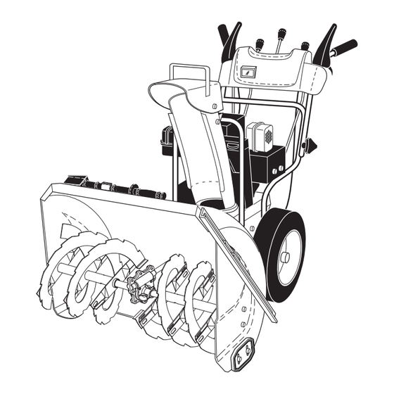
OPERATION KNOW YOUR SNOW THROWER READ THIS OWNER'S MANUAL AND ALL SAFETY RULES BEFORE OPERATING YOUR SNOW THROWER. Compare the illustrations with your snow thrower to familiarize yourself with the location of various controls and adjustments. Save this manual for future reference. These symbols may appear on your snow thrower or in literature supplied with the product. - Page 10 OPERATION AUGER GAS O LINE ELECTRIC DISCHARGE CHUTE CONTROL LEVER CONTROL FILLER CAP START LEVER BUTTON DEFLECTOR REMOTE DRIVE SPEED CONTROL LEVER MUF FLER CON TROL LEVER RECOIL (AUXILIARY) STARTER HANDLE CHUTE CHOKE DE FLEC TOR CON- TRACTION TROL DRIVE CONTROL LEVER PRIM ER...
- Page 11 OPERATION The operation of any snow thrower can result TO CONTROL SNOW DISCHARGE (See Fig. 13) in foreign objects thrown into the eyes, which can result in severe eye damage. Always wear WARNING: Snow throwers have ex- safety glasses or eye shields while operating posed rotating parts, which can cause your snow thrower or performing any ad just- severe injury from contact, or from ma-...
- Page 12 OPERATION USING THE CLEAN-OUT TOOL (See Fig. 15) • Slower speeds are for heavier snow and faster speeds are for light snow and transporting the snow thrower. It In certain snow conditions, the discharge chute may be- is recommended that you use a slower speed until you come clogged with ice and snow.
- Page 13 OPERATION NOTE: It is not recommended to operate the snow thrower BEFORE STARTING THE ENGINE over gravel or rocky surfaces. Objects such as gravel, rocks CHECK ENGINE OIL LEVEL (See Fig. 20) or other debris, can easily be picked up and thrown by the impeller, which can cause serious personal injury, property The engine on your snow thrower has been shipped from dam age or damage to the snow thrower.
- Page 14 OPERATION TO START ENGINE 5. Pull recoil starter handle quickly. Do not allow starter rope to snap back. Your snow thrower engine is equipped with both a 120 Volt A.C. electric starter and a recoil starter. The electric starter 6. When the engine starts, release the recoil starter han dle is equipped with a three-wire power cord and plug and is and slowly move the choke control to the “OFF”...
-
Page 15: Maintenance Schedule
MAINTENANCE GENERAL REC OM MEN DA TIONS LUBRICATION CHART The warranty on this snow thrower does not cover items ➀ SAE 5W-30 Motor Oil that have been sub ject ed to operator abuse or negligence. To receive full value from the warranty, operator must ➁... - Page 16 MAINTENANCE BELTS TO CHANGE ENGINE OIL Check belts for deterioration and wear after every 50 hours Determine temperature range anticipated before next oil of operation and replace if necessary. The belts are not change. All oil must meet API service classification SG–SL. ad just able.
-
Page 17: Service And Adjustments
SERVICE AND ADJUSTMENTS To replace the capscrew/shear bolts: WARNING: To avoid serious injury, before 1. Disengage all controls and move throttle control to performing any service or ad just ments: STOP position. Wait for all moving parts to stop. 1. Be sure throttle is in STOP position. 2. - Page 18 12. While your assistant slowly raises handles to rejoin fac tur er (OEM) belts avail able from your nearest Sears the auger hous ing and frame assembly, pull up on the service center/department.
- Page 19 Unhook carburetor problems, take your snow thrower to a Sears the rod from the control lever and move the spring at the service center/department.
-
Page 20: Storage
STORAGE Immediately prepare your snow thrower for storage at • Empty the fuel tank by starting the engine and letting it run until the fuel lines and car bu re tor are empty. the end of the season or if the unit will not be used for 30 days or more. -
Page 21: Troubleshooting
TROUBLESHOOTING See appropriate section in manual unless directed to a Sears service center/department. PROBLEM CAUSE CORRECTION Does not start 1. Fuel shut-off valve (if so 1. Turn fuel shut-off valve to OPEN position. equipped) in OFF position. 2. Safety ignition key 2. -
Page 22: Repair Parts
SNOW THROWER - - MODEL NUMBER 944.522442 REPAIR PARTS AUGER HOUSING / IMPELLER ASSEMBLY 2 (EXPLODED) 01.07.026-F NOTE: All component dimensions given in U.S. inches. 1 inch = 25.4 mm IMPORTANT: Use only Original Equipment Manufacturer (O.E.M.) replacement parts. Failure to do so could be hazardous, damage your snow thrower and void your warranty. - Page 23 SNOW THROWER - - MODEL NUMBER 944.522442 REPAIR PARTS AUGER HOUSING / IMPELLER ASSEMBLY PART DESCRIPTION 175321X479 IMPELLER 427148 GEARBOX ASSEMBLY 188909 BEARING 427146 IMPELLER PULLEY 442438 DISCHARGE BASE 178675X008 CORNER BRACKET 192199 CLEAN OUT TOOL 405400 TOOL CLIP 73800400 NUT 1/4-20 74780426 SCREW 1/4-20 X .625...
- Page 24 SNOW THROWER - - MODEL NUMBER 944.522442 REPAIR PARTS AUGER HOUSING / IMPELLER ASSEMBLY PART DESCRIPTION 404930X428 AUGER HOUSING 404933X479 SCRAPPER BAR 72270505 CARRIAGE BOLT 5/16−18 X .625 155377 NUT 5/16−18 3 (5x) 4 (5x) 01.07.003-A PART DESCRIPTION 420497X479 AUGER ASSEMBLY 30 LH 420498X479 AUGER ASSEMBLY 30 RH 01.07.019-A...
- Page 25 SNOW THROWER - - MODEL NUMBER 944.522442 REPAIR PARTS AUGER HOUSING / IMPELLER ASSEMBLY PART DESCRIPTION 420478 AUGER BEARING 411939 BEARING PLUG 179582 SCREW 5/16−18 X 1.00 01.07.024-B PART DESCRIPTION 435951 PLATE SKID PLASTIC HDPE 426589 NUT 5/16-18 LARGE HEX FLANGE BLK 72110510 CARRIAGE BOLT 5/16-18 X 1.25...
- Page 26 SNOW THROWER - - MODEL NUMBER 944.522442 REPAIR PARTS AUGER HOUSING / IMPELLER ASSEMBLY PART DESCRIPTION 181160X479 DRIFT CUTTER BAR 72270506 CARRIAGE BOLT 5/16−18 X .750 01.16.001-B 179246 PLASTIC WASHER 10040500 LOCKWASHER 5/16 128638 NUT 5/16−18 NOTE: All component dimensions given in U.S. inches. 1 inch = 25.4 mm IMPORTANT: Use only Original Equipment Manufacturer (O.E.M.) replacement parts.
- Page 27 SNOW THROWER - - MODEL NUMBER 944.522442 REPAIR PARTS CONTROL PANEL / DISCHARGE CHUTE PART DESCRIPTION 443328X428 CHUTE WELDMENT 178633X428 DEFLECTOR WELDMENT 420673 DEFLECTOR CONTROL ASSEMBLY 420325 DEFLECTOR SEAL 414280 KNOB BLACK 128415 POP RIVET 17501010 SCREW 10-24 X .625 430324 CHUTE SNOW SHIELD 419822X004...
- Page 28 SNOW THROWER - - MODEL NUMBER 944.522442 REPAIR PARTS CONTROL PANEL / DISCHARGE CHUTE PART DESCRIPTION 428272 LEVER/CABLE ROTATOR ASSEMBLY 17501010 SCREW 10-24 X .625 420678 ROTATOR HEAD 01.09.010-B 405932 ROTATOR PIVOT BRACKET 420675 PULLEY PIVOT 428273 CABLE ASSEMBLY ADJUSTABLE 428310 CABLE ASSEMBLY HEAT SHIELD NOTES:...
- Page 29 SNOW THROWER - - MODEL NUMBER 944.522442 REPAIR PARTS HANDLES PART DESCRIPTION 419800X479 PLOW HANDLE LH 419801X479 PLOW HANDLE RH 196944X007 PANEL BRACKET LH 196943X007 PANEL BRACKET RH 414515 HEATED HANDLE GRIP 74780512 CREW 5/16−18 X .750 74780524 SCREW 5/16−18 X 1.50 751153 NUT 5/16−18 155415...
- Page 30 SNOW THROWER - - MODEL NUMBER 944.522442 REPAIR PARTS HANDLES 01.08.002-J PART DESCRIPTION 412683X479 CONTROL PANEL 580687802 CONTROL LEVER LH 580687702 CONTROL LEVER RH 412679X008 TRACTION ROD ARM 426918X008 IMPELLER ROD ARM 412677 INTERLOCK BAIL 421613 SPACER 169675 RETAINER 17060410 SCREW 1/4-20 X .62 414280 KNOB BLACK...
- Page 31 SNOW THROWER - - MODEL NUMBER 944.522442 REPAIR PARTS HANDLES PART DESCRIPTION 580797701 IMPELLER ROD ASSEMBLY 580797901 TRACTION ROD ASSEMBLY 180445 SHIFTER ROD TOP 187716 SHIFTER ROD BOTTOM 180447 SPRING SLEEVE 580796201 SPRING CONTROL ROD 580802101 SPRING TRACTION ROD 72270505 CARRIAGE BOLT 5/16-18 X .750 155377 NUT 5/16-18...
- Page 32 SNOW THROWER - - MODEL NUMBER 944.522442 REPAIR PARTS HANDLES PART DESCRIPTION 412675X004 INTERLOCK SPRING 445291 INTERLOCK CAM 443215 TORSION SPRING 169675 RETAINER 17060410 SCREW 1/4−20 X .625 421252X004 INTERLOCK STOP 01.08.007-D PART DESCRIPTION 413927 CONSOLE PANEL 417760 SWITCH GRIP 175262 SCREW HX WHSR HEAD 10-24 X .25...
- Page 33 SNOW THROWER - - MODEL NUMBER 944.522442 REPAIR PARTS DRIVE 01.03.002-B PART DESCRIPTION 404923 AXLE ASSEMBLY (assy of 1a,1b) 404307 AXLE SHAFT 9465M1 ROLL PIN 3/16 X 1.50 402691 SPROCKET 444949 THRUST WASHER 179830 BEARING 146315 SCREW 5/16−18 X .625 17490508 SCREW 5/16−18 X .500 126875X...
- Page 34 SNOW THROWER - - MODEL NUMBER 944.522442 REPAIR PARTS DRIVE ITEM 42 EXPLODED 01.02.013-C NOTE: All component dimensions given in U.S. inches. 1 inch = 25.4 mm IMPORTANT: Use only Original Equipment Manufacturer (O.E.M.) replacement parts. Failure to do so could be hazardous, damage your snow thrower and void your warranty.
- Page 35 SNOW THROWER - - MODEL NUMBER 944.522442 REPAIR PARTS DRIVE PART PART DESCRIPTION DESCRIPTION 198875 SPEED SELECTOR ASSEMBLY 175344 BEARING 17501010 SCREW 10-24 X .625 178613 WHEEL HUB 402685X428 END PLATE 74760514 SCREW 5/16-18-.875 17490508 SCREW 5/16-18 X .50 12000012 RETAINER RING 57079 WASHER...
- Page 36 SNOW THROWER - - MODEL NUMBER 944.522442 REPAIR PARTS CHASSIS / ENGINE / PULLEYS PART DESCRIPTION 01.00.034-A - - - - - B&S ENGINE MODEL 21M314-2470-F2 418694X428 FRAME 150406 BOLT 3/8-16 428867 SCREW 5/16-18 X .750 PART DESCRIPTION 436146X428 ENGINE MOUNT PLATE 01.01.007-B NOTE: All component dimensions given in U.S.
- Page 37 SNOW THROWER - - MODEL NUMBER 944.522442 REPAIR PARTS CHASSIS / ENGINE / PULLEYS PART DESCRIPTION 408007 IMPELLER BELT 419744 TRACTION BELT 423723X479 IDLER ARM BRACKET 180523 IDLER PULLEY 426589 NUT 5/16-18 74780524 SCREW 5/16-18 X 1 .50 423990X479 IDLER BRACKET 17000510 SCREW 5/16-18 HEX 424297...
- Page 38 SNOW THROWER - - MODEL NUMBER 944.522442 REPAIR PARTS WHEELS 13 13 01.15.001-D PART DESCRIPTION 405161 COVER 184471 SHOULDER SCREW 12000045 RETAINER RING 192126 WHEEL DRIVER 182466 RETAINER RING 187622 WHEEL LOBE 194941 CLUTCH SLIDE 179139 SPRING 189282 SQUARE KEY 194940 AXLE LOBE 444949...
- Page 39 SNOW THROWER - - MODEL NUMBER 944.522442 REPAIR PARTS WHEELS PART DESCRIPTION 432340X428 WHEEL ASSEMBLY LH 432341X428 WHEEL ASSEMBLY RH 01.06.014-A PART DESCRIPTION 438446 CABLE BRACKET LH 438447 CABLE BRACKET RH 17490408 SCREW 1/4 -20 X .500 17600406 SCREW 1/4 -20 X .375 01.15.015-A NOTE: All component dimensions given in U.S.
- Page 40 SNOW THROWER - - MODEL NUMBER 944.522442 REPAIR PARTS BAG OF PARTS PART DESCRIPTION 198563 POWER CORD 169675 RETAINER PIN 180684X008 WRENCH 184505 REMOTE SPRING 179829 SHOULDER BOLT 1/4-20 191730 LOCKNUT 1/4-20 72250505 CARRIAGE BOLT 5/16-18 X 5/8 751153 LOCKNUT 5/16-18 73800600 LOCKNUT 3/8-16 19131316...
- Page 41 SNOW THROWER - - MODEL NUMBER 944.522442 REPAIR PARTS DECALS PART DESCRIPTION 181037 DECAL, DANGER 444776 DECAL 181035 DECAL, DANGER, DEFLECTOR 181042 DECAL, DANGER 181033 DECAL, INSTRUCTION 581430101 DECAL, CONS RT SPD/LEV/PS 581430102 DECAL, CONS LT WD/DEF 581454927 OWNER’S MANUAL, ENGLISH 581454931 OWNER'S MANUAL, FRENCH NOTE: All component dimensions given in U.S.
- Page 42 SNOW THROWER - - MODEL NUMBER 944.522442 REPAIR PARTS ENGINE, B&S MODEL NUMBER 21M314-2470-F2 1058 OPERATOR’S MANUAL 1330 REPAIR MANUAL 48 SHORT BLOCK 1329 REPLACEMENT ENGINE 1351 1026 358 ENGINE GASKET SET 358 ENGINE GASKET SET 1022 1427 718A 1171 1022 1029 1100...
- Page 43 SNOW THROWER - - MODEL NUMBER 944.522442 REPAIR PARTS ENGINE, B&S MODEL NUMBER 21M314-2470-F2 731A 601A 1252 1196 1288 1352 1318 601A 1251A 1127 1036 EMISSIONS LABEL 1251 1392 1230 1138 613A 668A...
- Page 44 SNOW THROWER - - MODEL NUMBER 944.522442 REPAIR PARTS ENGINE, B&S MODEL NUMBER 21M314-2470-F2 1119 1054 1210 1211 1023 1070 1022 1005 1070 121 CARBURETOR OVERHAUL KIT 1095 VALVE GASKET SET 1022...
- Page 45 SNOW THROWER - - MODEL NUMBER 944.522442 REPAIR PARTS ENGINE, B&S MODEL NUMBER 21M314-2470-F2 PART PART DESCRIPTION DESCRIPTION 794850 CYLINDER ASSEMBLY 690727 PLUG-WELCH 698340 KIT-BUSHING/SEAL 696139 VALVE-THROTTLE (MAGNETO SIDE) 694914 FLOAT-CARBURETOR 391086S SEAL-OIL (MAGNETO SIDE) 698780 TUBE-FUEL TRANSFER 799860 HEAD-CYLINDER 698781 GASKET-FLOAT BOWL 697690...
- Page 46 SNOW THROWER - - MODEL NUMBER 944.522442 REPAIR PARTS ENGINE, B&S MODEL NUMBER 21M314-2470-F2 PART PART DESCRIPTION DESCRIPTION 699854 SCREW (CONTROL COVER) 696709 GUARD-REWIND 691696 SCREW (PAWL FRICTION PLATE) 799719 CAP-FUEL 791850 CLAMP-HOSE (GREEN) 799863 TANK-FUEL 601A 691638 CLAMP-HOSE (PRIMER HOSE) 698783 BOWL-FLOAT 696758...
- Page 47 Engine Power Rating Information The gross power rating for individual gas engine models is labeled in accordance with SAE (Society of Automotive Engi- neers) code J1940 (Small Engine Power & Torque Rating Procedure), and rating performance has been obtained and cor- rected in accordance with SAE J1995 (Revision 2002-05).
- Page 48 02488 08.08.12 SR Printed in the U.S.A.
Need help?
Do you have a question about the Craftsman 1650 Series and is the answer not in the manual?
Questions and answers
Trying to find out where all of the springs are attached to. May need a service manual for sears craftsman 1650 snow blower
The Sears Craftsman 1650 Series snow blower has springs attached to various components, including:
- Spring/Link-Mechanical Governor (part number 796324)
- Spring-Friction (part number 691855)
- Pulley/Spring Assembly (part number 498144)
These springs are used for mechanical linkages, friction control, and pulley tensioning.
This answer is automatically generated