Table of Contents
Advertisement
Quick Links
Advertisement
Table of Contents
Troubleshooting

Related Manuals for Vertiv Liebert XDC


Summary of Contents for Vertiv Liebert XDC
- Page 1 Vertiv™ Liebert® XDC High Heat Density Precision Air Conditioner User Manual...
- Page 2 The products covered by this instruction manual are manufactured and/or sold by Vertiv. This document is the property of Vertiv and contains confidential and proprietary information owned by Vertiv. Any copying, use or disclosure of it without the written permission of Vertiv is strictly prohibited.
- Page 3 This page is intentionally left blank.
-
Page 4: Table Of Contents
Vertiv™ Liebert® XDC User Manual Table of Contents 1 Overview..............................................1 1.1. Product Introduction ......................................... 1 1.1.1. Energy Saving ........................................1 1.1.2. Diversified Terminal Types ..................................2 1.2. Model Nomenclature ......................................4 1.3. Product Appearance ....................................... 5 1.4. Main Components ........................................5 1.4.1. Compressor ..........................................5 1.4.2. - Page 5 Vertiv™ Liebert® XDC User Manual 2.6. System Installation Layout .....................................13 2.6.1. Overall System Layout ....................................13 2.6.2. System Installation Diagram ................................14 2.7. Installation of the Unit ......................................15 2.7.1. Mechanical Parameters ..................................15 2.7.2. Leveling the Cabinet ....................................16 2.7.3. Removing Leveling Feet and Fixing Cabinet ........................17 2.7.4.
- Page 6 Vertiv™ Liebert® XDC User Manual 4 System Startup and Commissioning ..............................36 4.1. Startup and Commissioning ..................................36 4.1.1. Preparation Before Commissioning ............................36 4.1.2. Vacuuming ........................................36 4.2. MCB Position ..........................................37 4.3. Static Refrigerant Charge ....................................37 4.4. Dynamic Refrigerant Charging ..................................37 4.5.
- Page 7 6.10. Mechanical Failure ......................................53 6.11. Electrical Failure ........................................53 7 Troubleshooting ..........................................54 Appendix I: Circuit Diagram of Vertiv™ Liebert® XDC ......................57 Appendix II: Alarm Output Menu ...................................58 Appendix III: Hazardous Substance Content ...........................59 Appendix IV: List of Maintenance Inspection Items (Semi-annual) ................60...
-
Page 8: Overview
Liebert XDC is highly effective and efficient in solving the problem of heat dissipation in server rooms with high heat density, and it is installed where cooling load changes drastically. -
Page 9: Diversified Terminal Types
1.1.2. Diversified Terminal Types The Vertiv™ Liebert® XD terminal air conditioners are arranged close to the server, and the diversified layout can be applied to different installation and use environments, as shown in Figure 1-2, Figure 1-3, and Figure 1-4. - Page 10 • Easy to Maintain Vertiv™ Liebert® XDC unit adopts a front door opening arrangement which helps in accessing all the live parts for the maintenance from the front side, and also enable the compact footprint of the unit.
-
Page 11: Model Nomenclature
1.2. Model Nomenclature The Vertiv™ Liebert® XDC is defined by twelve digits, as represented in Table 1-1. Table 1-1 Vertiv™ Liebert® XDC Nomenclature Digit 1, 2 Product Model X-treme High Density Digit 3 Cooling System Compressor Pump Digit 4, 5, 6 Cooling Capacity kW... -
Page 12: Product Appearance
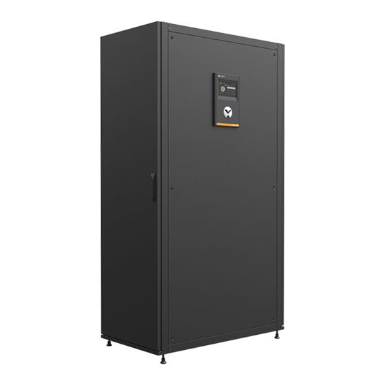
High Heat Density Main Unit in Room Figure 1-5 Air Conditioner Appearance Drawing 1.4. Main Components The Liebert XDC main unit mainly has a compressor, sight glass, safety control device, oil separator, compressor’s driver color screen and other supporting components. 1.4.1. Compressor... -
Page 13: Sight Glass
Figure 1-7 Sight Glass 1.4.3. Color Display Screen Liebert XDC main unit is equipped with a 7-inch HMI color screen display configuration that has a simple user interface and multi-level password protection which can effectively prevent the illegal operations. It has power-down self-recovery function, and high/low voltage protection function. -
Page 14: Safety Control Device
The unit uses a high-efficiency oil separator with oil separation efficiency of 90% or more, ensuring stable oil return from the compressor. 1.4.6. Remote Monitoring Software Liebert XDC air conditioner is provided with the standard industrial communication protocols such as Modbus RTU protocol (default), RS485 interface, and computer to computer serial communication. 1.4.7. Outdoor Unit For outdoor unit related information, please refer to Vertiv™... -
Page 15: Environmental Requirements
1.6. Environmental Requirements 1.6.1. Operating Environment The operating environment of the Vertiv™ Liebert® XDC main unit meets the requirements of GB4798.3-2007, as shown in Table 1-2. Table 1-2 Operating Environment Requirements Items Requirements Indoor 18 °C to 40 °C, RH<60% Ambient temperature -15 °C to 45 °C (Please contact Vertiv when outdoor... -
Page 16: Mechanical Installation
Keep the unit upright, place it indoors, keep it away from damp and low-temperature places, and avoid contact damage. 2.2. Maintenance Space Requirements The Liebert XDC unit can be installed in two ways: ‘Installation between rows’ and ‘installation in room’, customers can flexibly choose the respective model according to the actual application. • Maintenance Space Requirements User can choose installation between rows or installation in room, both of which require opening of the front door and the rear door for maintenance. -
Page 17: Unpacking And Inspection
• The main units that are installed between the rows, only require maintenance space at the front and rear sides. • In case of a special application, consult Vertiv local representative. 2.3. Unpacking and Inspection 2.3.1. Transportation and Handling 1. When transporting, the priority shall be given to rail or water transportation. If user choose road transportation then a road with better road conditions should be select to prevent excessive bumps. -
Page 18: Unpacking
While moving the indoor unit, keep the obliquity within the range of 75° to 105°, as shown in Figure 2-3. Figure 2-3 Handling Angle 2.3.2. Unpacking The unit’s cabinet is packed with honeycomb cardboard and stretch film. After moving the unit to the place closest to the final installation site, unpack it. -
Page 19: Inspection
2.5. Installation Notes 1. The Liebert XDC main unit is recommended to be installed between the rows or on the floor of the equipment room or the computer room. According to the diversified types of Vertiv™ Liebert® XD terminals, user can choose Vertiv™... -
Page 20: System Installation Layout
Note: Figure 2-6 shows a schematic diagram of Liebert XDC with a Terminal Fan, in actual practise the number of fans may be more than 2. Note: Each system of the Liebert XDC main unit can be equipped with multiple cooling terminals. In... -
Page 21: System Installation Diagram
2.6.2. System Installation Diagram The bottom piping of Vertiv™ Liebert® XDC unit is in the outlet mode that supports at least two cooling systems. The installation and application methods of these two cooling systems are same, but the pipelines are completely independent. -
Page 22: Installation Of The Unit
Note: Refer to the installation diagram to ensure that the relevant pipeline is at least 1/100 inclination. Note: Refer to the installation diagram. When the outdoor unit is higher than Liebert XDC, or the terminal is lower than Liebert XDC, pay attention to install an oil trap on the air pipe. -
Page 23: Leveling The Cabinet
Note: The total cabinet height including leveling feet is 2000 mm; and total height excluding leveling feet is 1944mm. 2.7.2. Leveling the Cabinet The followings are steps to level the Liebert XDC cabinet 1. Place the unit on the open floor of the installation site. -
Page 24: Removing Leveling Feet And Fixing Cabinet
2.7.3. Removing Leveling Feet and Fixing Cabinet To avoid personal injury and damage to the unit, the operation should be performed by two trained professional. ITEMS DESCRIPTION ITEMS DESCRIPTION Front top fixing hole Front bottom fixing hole Rare top fixing hole Rare bottom fixing hole Figure 2-11 Cabinet Fixing Holes •... - Page 25 • Location of the Piping Outlet Position and Sizes on Bottom Plate Table 2-4 shows the outlet piping specifications of the Vertiv™ Liebert® XDC host. Table 2-4 Liebert XDC Piping Outlet Specifications Pipeline Type Pipe Size (OD, mm) Suction Line...
-
Page 26: Parallel Connecting Cabinets
2.7.4. Parallel Connecting Cabinets If the Vertiv™ Liebert® XDC is installed between the rows, it needs to be combined with the server rack. There are connecting parts which helps in connecting the cabinet in parallel to the server racks, where users can easily fix them with adjacent cabinets. -
Page 27: Unit Piping Installation
ITEMS DESCRIPTION Discharge pipe Branch suction pipe Liquid pipe Liquid distributor Sight glass Branch liquid pipe Suction pipe Ball valves Suction distributor Dry filter for XDO and XDV Figure 2-14 Engineering Pipeline Diagram Vertiv™ | Liebert® XDC | User Manual... - Page 28 H3 Main unit at bottom Height difference between terminals H4 Note: For the applications with larger piping lengths or height differences, consult Vertiv local representative. Example The calculation of the piping equivalent length are as follows: For the discharge pipe L1, if the actual length is 30 m, then 90° elbows; two oil traps are used; and the pipe diameter is 25 mm, the equivalent length of the discharge pipe is: 30 + 0.5 x 10 + 3.4 x 2 = 41.8 (m)
-
Page 29: Dimension Refrigerant Piping
2.8.2. Dimension Refrigerant Piping According to the rated cooling capacity and equivalent piping length of the Vertiv™ Liebert® XDC with the rated single system, select the specifications of discharge pipe L1, Liquid return pipe L2, and Suction pipe L3, from... - Page 30 Note: The sizes of copper piping are shown in Table 2-11, it must be a hard pipe (Y) specified in the national standard GB/T18033-2007. If a semi-hard or soft copper pipe is used at the site, consult Vertiv technical team for the wall Mechanical Installation...
-
Page 31: Branch Manifold
Improper selection of the piping material may cause system leakage or piping burst, contact Vertiv local representative for more details. 2.8.3. Branch Manifold As shown in Figure 2-15 Figure 2-16, when connecting the main piping and the branch piping, a branch manifold installation is required. -
Page 32: Connecting Refrigerant Piping
2.8.4. Connecting Refrigerant Piping When connecting the refrigerant pipeline, the following requirements must be strictly observed: 1. Before brazing all the copper pipes, release the air present in the piping by opening each ball valves at least for 15min to avoid absorption of moisture with the compressor’s lubricating oil. -
Page 33: Air Tightness Test
Vertiv™ Liebert® XDC systems, a total of 4 Nos; open all the ball valves at theVertiv™ Liebert® XD cooling terminal. Once all ball valves are open, each system is divided into two sections: a) The inside of Liebert XDC is the low-pressure section. Check the pipeline for the sign of leakage which including compressor, oil separator and connecting piping. - Page 34 Note: Ensure to select the appropriate refrigerant oil recommended by manufacturer, otherwise the compressor will be damaged. Note: For refrigerant oil charging details of other Vertiv™ Liebert® XDC systems, contact Vertiv local representative. For any consequences resulting from inferior quality refrigerant, Vertiv does not assume warranty responsibility.
-
Page 35: Remove Transportation Fixing Plate Of Compressor
Note1: Remove the three U-shaped fixing plates after installation, and then restore the bolts and washers in reverse sequence of the disassembly process. Note2: The fastening torque of the bolts is (12±1) Nm. ITEMS DESCRIPTION U-Shape Plate Figure 2-20 “U”-shaped Fixing Plate Vertiv™ | Liebert® XDC | User Manual... -
Page 36: Mechanical Installation Checklist
The piping connecting the indoor and outdoor units have been installed properly, and the ball valves of the condenser, the Liebert XDC unit, and the terminal have been fully opened. The cold drain pipe at the cooling terminal is firmly connected. -
Page 37: Electrical Installation
This chapter introduces the electrical installation of Vertiv™ Liebert® XDC unit, including brief introduction of key components, installation notes, cabling and electrical inspection for the unit. Note: Liebert XDC unit is a professional equipment, used in industrial, commercial or other professional environment, and is not sold to the general public. -
Page 38: Cabling Of The Unit
Figure 3-1 Electrical Control Box and User Cabling Open the front door of Vertiv™ Liebert® XDC unit and the user can see the specific distribution position of the low-voltage components. The detailed distribution information of low-voltage electrical components is provided according to the labels... -
Page 39: Connection Of Unit Power Supply Cables
Condenser breaker Figure 3-2 Unit Electric Control Box 3.2.2. Connection of Unit Power Supply Cables The specific location of the power supply interface of the Vertiv™ Liebert® XDC unit is shown in Figure 3-2. L1~L3, N and PE are connected to the corresponding ends of the external power supply terminals respectively. A certain margin for the incoming cable should be provided to fix it on the cable fixing clamp, which is fixed on the inner panel of the unit. -
Page 40: Control Cables Connections
3.3. Control Cables Connections Figure 3-3 shows the location of the cabling terminals used for field cabling/wiring. Before connecting the control cables, the person who carries out cabling work must take corresponding anti-static measures. ITEMS DESCRIPTION ITEMS DESCRIPTION Customized Alarm RS-485 interface Remote On/Off RS-485 to condenser... - Page 41 CANH/CANL on each terminal block of the terminal. RS485 communication is used between the Liebert XDC unit and the condenser, and the user needs to connect the cables on site, lead the cables from the host RSA/RSB terminal, and then connect in series with the J11 terminal of the condenser.
-
Page 42: Electrical Inspection Checklist
All cables and circuit connectors have been tightened, and the tightening screws are not loose After confirming the above points, user can start the commissioning. Users are prohibited from powering on the unit before the professional and technical personnel authorized from Vertiv have checked and confirmed the electrical connections. Electrical Installation... -
Page 43: System Startup And Commissioning
4.1.1. Preparation Before Commissioning • Mechanical Part 1. According to the instruction label at the valve, ensure that all valves of the Vertiv™ Liebert® XDC unit and all cooling terminals are open. 2. The refrigerant piping system has passed the air tightness test and confirmed that there is no leakage. -
Page 44: Mcb Position
4.2. MCB Position The positions of the main isolation switch and MCB of the dual system unit are shown in Figure 3-2, distinguish them according to the label instructions on the actual cabinet. 4.3. Static Refrigerant Charge After the vacuuming is completed, the refrigerant can be charged statically: 1. -
Page 45: Commissioning Inspection Checklist
Table 4-1 Commissioning Inspection Checklist Inspection Items Results All output functions are automatic The temperature and humidity settings and control accuracy are correct Whether there is any abnormal alarm Other settings are correct Vertiv™ | Liebert® XDC | User Manual... -
Page 46: Color Display Screen Operating Instructions
6. The unit has a CAN interface and adopt CAN communication protocol. Note: The color display screen used by Liebert XDC unit is a resistive screen. When the user touches the screen to perform related operations, if the screen does not respond in time, thus user needs to use fingertips to try again. -
Page 47: Color Screen Interface
• The middle part displays the main operating status of the unit; the rightmost part displays the output status of the main adjustment components of the unit (such as compressor, outdoor unit), as shown in Figure 5-3 Figure 5-4. Figure 5-3 Color Screen Interface-locked Vertiv™ | Liebert® XDC | User Manual... - Page 48 Figure 5-4 Color Screen Interface-unlocked • When browsing the menu, tap the corresponding menu key to view related parameters. The function description of each touch key on the interface is provided in Table 5-1. Table 5-1 Touch Key Function Description Touch Key Function Description Main interface...
-
Page 49: Operation Example
CLR (clear) key to change. Note: In the password interface, directly press the enter key without typing any password, user can view the set value of each menu, but user cannot change any parameters. Vertiv™ | Liebert® XDC | User Manual... -
Page 50: Other Interfaces
5.4. Other Interfaces 5.4.1. Alarm Status Click the Alarm Status icon to enter the interface shown in Figure 5-6, including current alarms and historical alarms. • Active alarm The Active Alarm page is used to monitor the current alarm status record of the air-conditioner unit, prompting no alarm or specific alarm status information. -
Page 51: Main Unit Menu
Figure 5-7 Figure 5-8, the unit icon on the left is lit, user can view the main unit operating status and set related parameters. Figure 5-7 Menu Setting Interface Figure 5-8 Run Information Interface Vertiv™ | Liebert® XDC | User Manual... -
Page 52: Terminal Menu
5.4.3. Terminal Menu Click the Terminal icon to enter the interface shown in Figure 5-9, Figure 5-10, and Figure 5-11. The left terminal icon is lit, user can view the running status of the terminal and set related parameters. Figure 5-9 Basic Terminal Status Interface Figure 5-10 Terminal Run Status Interface Color Display Screen Operating Instructions... -
Page 53: Run Time
Figure 5-11 Terminal Alarm Setting Interface 5.4.4. Run Time Figure 5-13 shows the RUN Time interface of the unit. Figure 5-12 Run Time Interface Vertiv™ | Liebert® XDC | User Manual... -
Page 54: About
5.4.5. About Figure 5-14 shows the About interface of the unit. Figure 5-13 About Interface Color Display Screen Operating Instructions... -
Page 55: System Operation And Maintenance
Vertiv™ Liebert® XDC unit, including routine maintenance inspections, system troubleshooting tests, and maintenance of filter net, fan components, cooling systems, and drainage systems. It is recommended that the load of Liebert XDC system should not be less than 30%. If the •... -
Page 56: Routine Maintenance Inspection (Semi-Annual)
6.2. Routine Maintenance Inspection (Semi-annual) Table 6-2 provides the details of semi-annual routine maintenance and inspection items of Vertiv™ Liebert® XDC unit. Table 6-2 Semi-annual Routine Inspection Items List Parts Inspection Items Remark Check for any sign of leakages Compressor part... -
Page 57: System Troubleshooting Test
10. Adjust the setpoints, and detect the action of each functional component according to the control logic. 11. Simulate and detect the running status of the protection units such as the Vertiv™ Liebert® XDC unit. 12. Check whether the cabling and numerical display of each sensor are normal. -
Page 58: Cooling System
“liquid impact” and break the scroll of the scroll compressor. Note: If abnormal opening or adjustment of the electronic expansion valve is found at the application site, contact Vertiv local representative and Vertiv technical support. -
Page 59: Terminal Fan
Refer to the related information in Maintenance in “Vertiv™ Liebert® LVC Condenser User Manual”. 6.9. Compressor The Vertiv™ Liebert® XDC units use variable capacity compressors, which are highly reliable and require engineering construction to strictly follow correct procedures. The compressor motor is rarely burned out due to insulation failure. In the event that the motor is indeed •... -
Page 60: Mechanical Failure
Note: The replacement of the compressor needs to be carried out under the guidance of professionals. For replacement, contact Vertiv technical support engineer. Note: The damage caused to the compressor due to improper cleaning will not be covered in the warranty and related details are mentioned in the warranty clause. -
Page 61: Troubleshooting
Note: When using jumpers for troubleshooting, always remember to remove the jumpers after the repair work is completed. The remaining connected jumpers may overrun the control function and cause equipment damage. Table 7-1 provides the troubleshooting and treatment of each component of Liebert XDC unit. Table 7-1 Troubleshooting Compressor and Cooling System Symptom... - Page 62 Symptom Possible Cause Items to be Checked or Handling Method Check the line voltage after checking the circuit MCB tripped breaker and contactor Compressor built-in protector Check whether the compressor coil is open. If open, disconnected wait for the coil to cool down and reset automatically Is there an alarm for low exhaust air superheat/high Detect exhaust air temperature sensor temperature...
- Page 63 • Check whether the evaporator and condenser fan overheated of the terminal are operating normally Adjust the setting of the electronic expansion valve of Suction superheat is too high the terminal or add a proper amount of refrigerant Vertiv™ | Liebert® XDC | User Manual...
-
Page 64: Appendix I: Circuit Diagram Of Vertiv™ Liebert® Xdc
Appendix I: Circuit Diagram of Vertiv™ Liebert® XDC NOTES : 1. ALL FIELD WIRING TO BE PER LOCAL CODES. USE COPPER CONDUCTORS ONLY. FACTORY MOUNTED MAIN UNIT SWITCH 2. SEE INSTALLATION AND USER MANUAL(S). 3. JUMPER TO BE REMOVED WHEN OPTIONAL COMPONENT IS USED. -
Page 65: Appendix Ii: Alarm Output Menu
Common alarm polarity Reset alarm lock Clear alarm history Remarks: Self defined type: 0: other; 1: smoke alarm; 2: fire alarm. Except for “Others”, the self defined alarm input type cannot be repetitive. Vertiv™ | Liebert® XDC | User Manual... -
Page 66: Appendix Iii: Hazardous Substance Content
Appendix III: Hazardous Substance Content Date: _____________________________ Prepared by: ____________________________ Model: _____________________________ Serial No.: ______________________________ Filter net of terminal: Cooling cyclic system ___ 1. Check if the filter net is damaged or blocked ___ 1. Check the suction pressure ___ 2. Check the filter net blockage switch ___ 2. -
Page 67: Appendix Iv: List Of Maintenance Inspection Items (Semi-Annual)
___ 6. The temperature switch is at the specified setting value ___ 7. The refrigerant pipeline is properly supported ___ 8. Check and fix the circuit connector Signature_________________________________________________________ Note: Please copy this form for record archive. Vertiv™ | Liebert® XDC | User Manual... -
Page 68: Appendix V: Toxic And Hazardous Substances Or Elements
SJ/T11363-2006. Vertiv is committed to the design and manufacture of environmentally friendly products. We will continue to reduce and eliminate toxic and hazardous substances in our products through continuous research. The following components or... - Page 69 Connect with Vertiv on Social Media https://www.facebook.com/vertiv/ https://www.instagram.com/vertiv/ https://www.linkedin.com/company/vertiv/ https://www.twitter.com/vertiv/...
- Page 70 Vertiv.com © 2021 Vertiv Group Corp. All rights reserved. Vertiv™ and the Vertiv logo are trademarks or registered trademarks of Vertiv Group Corp. All other names and logos referred to are trade names, trademarks or registered trademarks of their respective owners. While every precaution has been taken to ensure accuracy and completeness here, Vertiv Group Corp.
Need help?
Do you have a question about the Liebert XDC and is the answer not in the manual?
Questions and answers