Table of Contents
Advertisement
Advertisement
Table of Contents

Subscribe to Our Youtube Channel
Related Manuals for Vertiv Liebert AHU


Summary of Contents for Vertiv Liebert AHU
- Page 1 Liebert® AHU Precision Air Conditioning User Manual...
- Page 2 No part of this document may be reproduced or transmitted in any form or by any means without the prior written consent of Vertiv Co.
- Page 3 Purpose of the Document This document applies to the series of precision air conditioners and cooling solutions which maintain optimal environmental control of technological ecosystems at minimal operating costs. This document gives an overview of the specifications, installation, commissioning, and maintenance procedures with troubleshooting from the user perspective. The figures used in this document are for reference only.
- Page 4 Use of a leak detection system for the unit and system supply lines are recommended by Vertiv.
-
Page 5: Table Of Contents
Vertiv™ | Liebert® AHU | User Manual Table of Contents 1 Product Overview ............................................1 1.1. Product Introduction ..........................................1 1.2. Model Description .............................................1 1.3. Model Nomenclature ..........................................2 1.4. Components ..............................................4 1.4.1. 9-Inch Color Display ........................................5 1.4.2. Remote Monitoring Software ..................................6 1.4.3. - Page 6 Vertiv™ | Liebert® AHU | User Manual 2.1.2. Unpacking ............................................9 2.1.3. Inspection ............................................10 2.2. Installation Preparation (Site Preparation) ..............................10 2.2.1. Equipment Room Requirements ................................10 2.2.2. Installation Space Requirements ................................11 2.2.3. Maintenance Space Requirements ................................. 11 2.2.4. Installation Tools ........................................12 2.2.5.
- Page 7 Vertiv™ | Liebert® AHU | User Manual 3 Touchscreen Display ..........................................30 3.1. Touchscreen Display and User Interface ................................30 3.2. Touchscreen Status Dial .........................................32 3.2.1. Dial Background-Color Status Indication ............................32 3.3. Control Header ............................................34 3.3.1. Powering-On iCOM and Logging-in/Unlocking Controls ....................34 3.3.2.
- Page 8 Vertiv™ | Liebert® AHU | User Manual 3.4.8. Managing Run Hours for a Component ............................41 3.4.9. Setting Run Hours to Zero ....................................41 3.4.10. Viewing Teamwork, Stand-by, Cascade and Operating Status ................42 4 ICOM Embedded Unity Setup Guide ..................................43 4.1.
- Page 9 Vertiv™ | Liebert® AHU | User Manual Appendix III: User Menu ............................54 Appendix IV: Table Names and Content of Harmful Substances in Products ......... 55 Appendix V: Routine Maintenance Inspection Items (Monthly) ..............56 Appendix VI: Routine Maintenance Inspection Items (Semi-Annual) ............. 57...
-
Page 10: Product Overview
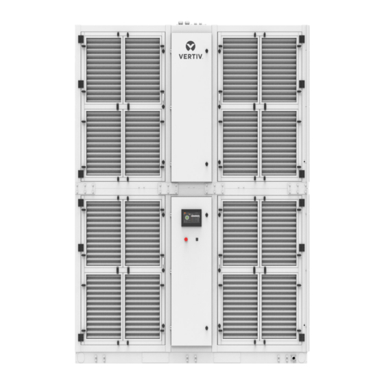
The appearance of the AHU model is shown in Figure 1-1. Figure 1-1 AHU Model Vertiv™ | Liebert® AHU | User Manual... -
Page 11: Model Nomenclature
1.3. Model Nomenclature The AHU series model is fully defined by 25 digits, as represented in Table 1-1. Table 1-1 AHU Model Nomenclature 23 24 Digit 1,2 Product Model Digit 14 Filtration Fan Array CRAC Digit 3, 4, 5 Air Volume 65 x 1000 (CMH) Digit 15 Special Power option None... - Page 12 Digit 22 Special Requirements Digit 24 Order Identifier SFA - None Factory Code Condensate Pump Digit 25 Order Identifier Digit 23 Order Identifier Factory Code Factory Code Note1: The standard configuration is highlighted in bold italics. Vertiv™ | Liebert® AHU | User Manual...
-
Page 13: Components
1.4. Components An overview of the main components, optional components, and features of the AHU is mentioned in this section. AHU components include the indoor unit and remote monitoring software. Figure 1-2 shows the main components of AHU. Figure 1-2 The main components AHU includes EC Fan, Filer, Coil, EPIV, Air Damper, and iCOM Controller. -
Page 14: 9-Inch Color Display
Figure 1-3. The operation of the unit becomes simpler and more convenient, and the status view of the unit is more visualized. Figure 1-3 iCOM Controller Display Vertiv™ | Liebert® AHU | User Manual... -
Page 15: Remote Monitoring Software
1.4.2. Remote Monitoring Software AHU interface with the BMS system through Modbus/ SNMP/ BACnet communication protocol by unity card, which enables AHU to communicate with the host computer and receive the control instructions from the host software. 1.4.3. Dual Power Supply- ATS The dual power ATS can automatically detect both the power sources (source 1 &... -
Page 16: Picv
Operation voltage range 380-415 V, 3 Ph + N~50/60 Hz Note: Contact Vertiv local representative when operating in the following conditions: 1. The voltage of the air conditioning unit is beyond the range of the operating voltage. 2. The altitude is higher than 1000 m. -
Page 17: Installation
2 Installation The installation process consists of the following procedures, namely: • Pre-installation • Installation Preparation • Mechanical Installation • Electrical Installation 2.1. Pre-installation 2.1.1. Transportation and Movement Railways and shipping are the preferable transport options for the AHU. If transport by rail or by ship is unavailable, transport by road is recommended. -
Page 18: Unpacking
The unit is fixed onto the base pallet with an M8×40 bolts screw, as shown in Figure 2-3. Use a 17 mm open-end spanner, ratchet spanner, or sleeve to remove the fixing bolts. Vertiv™ | Liebert® AHU | User Manual... -
Page 19: Inspection
Check that the fittings are complete and the components are intact against the packing list. If any parts are missing or damage is found, please report immediately to the local offices of the carrier and Vertiv. 2.2. Installation Preparation (Site Preparation) AHU is streamlined for maintaining a favorable environment for equipment rooms, computer rooms, and similar ecosystems. -
Page 20: Installation Space Requirements
Note1: It is recommended that the site preparation is defined as per the requirements. However, if these requirements are not met, Vertiv recommends that rectifications be made on the site so that it complies with the specified requirements and conditions. -
Page 21: Installation Tools
Table 2-1 Normal Maintenance Space (unit: inch/mm) Product Type Front inch FA065HC1NE09020F1070P0000 1100 43.3” FA065HC1NE09020M1070P0000 1100 43.3” 2.2.4. Installation Tools The following Table 2-2 shows the generic tool sets and utilities used in the installation and maintenance process. Table 2-2 List of Generic Tools Name Drawing Name... -
Page 22: System Arrangement During Installation
Field piping (by technical personnel) Note3: The single system is used as an example. Note4: Components (marked with *) are not supplied by Vertiv but are recommended for proper circuit operation and maintenance. Vertiv™ | Liebert® AHU | User Manual... -
Page 23: Mechanical Parameters
2.3. Mechanical Parameters 2.3.1. Unit Dimension and Weight The dimensions and net weight of the units are depicted in Figure 2-5, Figure 2-6 & Figure 2-7 Table 2-3 respectively. Figure 2-5 AHU Outline Table 2-3 AHU Dimension and Net Weight Dimensions Net Weight Product Number... - Page 24 Figure 2-6 Upper Section (unit: mm) Figure 2-7 Lower Section (unit: mm) Vertiv™ | Liebert® AHU | User Manual...
-
Page 25: Position And Dimension Of Top Cover
Table 2-4 Plenum Dimensions Gross D (depth) W (width) H (height) weight weight Types inch inch inch Upper 1600 63.0 2800 110.2 1740 68.5 1100 1400 FA065HC1NE09020F1070P0000 Lower 1600 63.0 2800 110.2 1860 73.2 1300 1400 Upper 1600 63.0 2800 110.2 1740 68.5... -
Page 26: Position And Dimensions Of Steel Base
Figure 2-9 Inlet and Outlet Pipe Flange (unit: mm) 2.3.4. Position and Dimensions of Steel Base The base dimensions are shown in Figure 2-10. Figure 2-10 The Dimensions of Steel Base (unit: mm) Vertiv™ | Liebert® AHU | User Manual... -
Page 27: Position And Dimensions Of Air Outlet
2.3.5. Position and Dimensions of Air Outlet The position and dimensions of the air outlet are shown in Figure 2-11 respectively. Figure 2-11 Air Outlet (unit: mm) 2.3.6. Position and Dimension of Air Inlet The electric box is embedded on the return air side, and the electric box door of the lower cabinet is equipped with a color display, emergency switch, and light switch. -
Page 28: Installation
The floor stand is to be prepared by the installation team according to the dimensions, weight, and height of the unit to en- sure that the structure is rigid, the floor stand should be sized according to Figure 2-13. Vertiv™ | Liebert® AHU | User Manual... - Page 29 Figure 2-13 Floor Stand Install the lower section on the floor stand, and then connect the base and the lower section with seismic restraint brackets (SRB). Figure 2-14 SRB Installation...
- Page 30 Figure 2-15 Hoisting Tooling 2) Remove the wooden base at the bottom of the upper cabinet. Dismantle the L-shaped connector to separate the wooden base from the unit. 3) Install eyelet and sling. Figure 2-16 Eyelet Vertiv™ | Liebert® AHU | User Manual...
- Page 31 4) The unit needs to be protected before hoisting. Pad some thick EPE or other things between the sling and the frame of the unit. After completing the above steps, start hoisting. During the hoisting process, it is necessary to ensure that the force in all directions is consistent and the unit is stable. It is necessary to protect the aluminum frame with some paper or wood.
- Page 32 For the sheet metal structure unit, after fixing the external connections of the unit, 4 M12 combination bolts are used to fix the unit inside the unit. The fixing positions and bolts are shown in the Figure 2-19. Vertiv™ | Liebert® AHU | User Manual...
-
Page 33: Pipe Installation
Figure 2-19 Combination bolt position Figure 2-20 Horizontal group installation 2.3.8. Pipe Installation Condensed Drain Piping Connection of Unit. The condensate water pan of the upper cabinet drains to the drain pan of the lower cabinet, and the drain pan of the lower cabinet drains to the outside of the unit. The cooling water inlet and outlet pipes are connected, the cooling water inlet and outlet pipes are connected by flanges, and the flanges are sealed with sealing rings. -
Page 34: Installation Inspection
The airflow distribution system has been installed in each room (e.g. raised floor/grill, duct, etc.) The upflow unit must have a plenum or air duct connection, and after installation the fan and heater shall not be accessible Everything is checked and verified, follow the electrical installation. Vertiv™ | Liebert® AHU | User Manual... -
Page 35: Electrical Installation
Before the wiring, use a volt-meter to measure the power supply voltage and ensure that the power supply has been switched off. The applicable grid for this air conditioner, TN, TT star connection power system; consult Vertiv local representative for other connections. -
Page 36: Connecting Control Cables
Figure 2-23. Description Description 89/90 is the feedback interface of air damper 93/94 is the RS485 interface of ATS 91/92 is the feedback interface of the EPO Figure 2-23 View of Terminal Block/Row Vertiv™ | Liebert® AHU | User Manual... -
Page 37: Connecting Belt Type Leak Detector
Note: Before connecting the control line, it is mandatory to perform the corresponding anti-static measures. 2.4.4. Connecting Belt Type Leak Detector Each unit is equipped with a 10m long belt type water leakage detector, and the water leakage detection transmitter has been installed in the electric box of the lower section. -
Page 38: Check The Installation
The control cables are well connected All the cables connections are fastened, with no loose screws Do not power-on the unit, unless the unit has been checked and confirmed by Vertiv Personnel/ Vertiv Service Team. Vertiv™ | Liebert® AHU | User Manual... -
Page 39: Touchscreen Display
3 Touchscreen Display Liebert® iCOM offers the highest capability for unit control, communication, and monitoring of Liebert Thermal Management Units. It is available as factory-installed on new units and assemblies. 3.1. Touchscreen Display and User Interface The Liebert iCOM touchscreen, user interface speed set up, installation, and simplified control of Liebert® AHU units literally putting cooling-system monitoring and management at your fingertips. - Page 40 Teamwork-mode icon: In a panel with status content the Teamwork Mode icon indicates the mode selected Control header: Control to access the user and service menus. See Control Header Status Header. Displays the alarm status, unit identification, and the current date and time Vertiv™ | Liebert® AHU | User Manual...
-
Page 41: Touchscreen Status Dial
3.2. Touchscreen Status Dial The dial in the primary-control panel is divided into four customizable read-only sections that display setpoints and environmental conditions for the unit status at a glance. See Figure 3-2, the center of the dial displays sensor readings and changes color according to the alarm thresholds as the readings rise and fall. - Page 42 Average Rack Temp High remote temperature Low remote temperature Blue Max Rack Temp High remote temperature Low remote temperature Blue Min Rack Temp High remote temperature Low static pressure Blue Static Pressure High static pressure Vertiv™ | Liebert® AHU | User Manual...
-
Page 43: Control Header
3.3. Control Header The control header contains the controls to access the user and service settings. The display is locked when started initially and resumed after a period of inactivity. 3.3.1. Powering-On iCOM and Logging-in/Unlocking Controls iCOM is powered-ON when power is switched ON at the cooling unit’s disconnect switch and you activate the display by touching it. - Page 44 “On/ Closed” or if one is “Off/ Open”, the unit turns off. • Turned-off by remote monitoring system. MONITORING OFF • Check the remote monitoring device or call Vertiv technician support for assistance. BACK-DRAFT Unit is non-operational, but EC fan is operating as a back-draft damper.
-
Page 45: Powering-Off The Thermal Management Unit
3.3.3. Powering-Off the Thermal Management Unit 1. Press then > Turn Unit Off, then Turn Unit Off panel opens. 2. Press ‘Turn Unit Off’, the unit begins a power-Off countdown then powers-Off. Note: User must be logged-in to access the menu options. See Powering-on iCOM and Logging-in/ Unlocking Controls. 3.3.4. -
Page 46: Accessing The User And Service Functions
• Technical Support-contact information for the cooling unit and iCOM display 3. Alarm/Event Setup: Opens the ALARMS & EVENTS panel. 4. Economizer: Opens the panel for the economizer installed on the cooling unit. Vertiv™ | Liebert® AHU | User Manual... -
Page 47: Advanced Menu
5. BMS & Teamwork Setup: Opens the BMS & Teamwork Setup menu: • U2U Setup • Teamwork/Standby • BMS Setup 6. Scheduler: Opens the SCHEDULER panel. 7. Options Setup: Opens the OPTIONS SETUP panel. 8. Auxiliary Device Setup: Opens the Auxiliary Device Setup menu: •... -
Page 48: User Operation
Touch the screen to silence an audible alarm. If the alarm is non-latching, the alarm silences when the condition clears. Note: The audible alarm must be enabled in display options to make a sound. Vertiv™ | Liebert® AHU | User Manual... -
Page 49: Acknowledging Alarms
3.4.5. Acknowledging Alarms Depending on the notification settings, alarms and warnings must be acknowledged or reset. An event is active as long as it is unacknowledged, except for the network-failure events described in Table 3-5. Once acknowledged, an event remains active until the situation that triggered the event is resolved, see Table 3-4 for event-status indicators. -
Page 50: Viewing Sensor Data
1. On the RUN HOURS panel, press to check each box in the Total Run Hours column next to the component (s) to reset. The Set to Zero button is enabled. 2. Press Set to Zero, the total run hours for selected component (s) will set to zero. Vertiv™ | Liebert® AHU | User Manual... -
Page 51: Viewing Teamwork, Stand-By, Cascade And Operating Status
3.4.10. Viewing Teamwork, Stand-by, Cascade and Operating Status In the main User panel, the Teamwork Mode icon indicates the mode selected, see Figure 3-5. To view the teamwork details 1. Press the Teamwork-mode icon. 2. The teamwork dialog opens display the teamwork mode, number of units in stand-by, and number of operating units. Description No teamwork Mode 1- Parallel Teamwork... -
Page 52: Icom Embedded Unity Setup Guide
After the iCOM controller has rebooted, it may take at least three more minutes for Embedded Unity to fully reboot. If it doesn’t reboot, click Refresh from the BMS & Teamwork Setup-IS-Unity Setup page of the Service menu. Figure 4-1 Internal Control Board Connections Vertiv™ | Liebert® AHU | User Manual... -
Page 53: Creating Administrator Account
Figure 4-2 iCOM Service Screen 4.4. Creating Administrator Account The Embedded Unity service requires the end-user to create a new username and password to authenticate any Unity configuration change. The iCOM controller stores the login credentials used for all configuration changes. The stored username/password must match that of a user account with the Embedded Unity service. -
Page 54: Configuring Embedded Unity For Bms Connectivity
For further assistance setting up the Embedded Unity service, see the on-board help. Click the ? on the right side of the web UI to open the Help menu and search for Unity from the iCOM Help Search bar. Vertiv™ | Liebert® AHU | User Manual... -
Page 55: System Operation And Maintenance
5 System Operation and Maintenance Regular system maintenance is critical to ensure the reliability and effectiveness of the product. This chapter describes AHU system maintenance, the content includes routine maintenance inspection items, check the electrical connections, control devices visual inspection, filter maintenance guide. During the running of AHU, there may be lethal voltage within the device. -
Page 56: Routine Maintenance Inspection Items (Semi-Annual)
Check the water flow Check the hydraulic resistance Check whether there is deformation on the fan impeller Check whether the fan and fan shroud is firmly fixed Check whether the bearing is worn Vertiv™ | Liebert® AHU | User Manual... -
Page 57: Self-Diagnostic System
Check whether the rotating blades will cause friction on the nearby metal parts Listen to whether there is abnormal noise Observe whether there is obvious vibration in the fan Examine fuse and circuit breaker Check and fasten the circuit connector Control system Check the contactor pull-on status Check the control program... -
Page 58: Filter Maintenance Guide
3. If you are unsure about the setting point, consult with Vertiv before using a filter of a different model to replace the old one. -
Page 59: Diagnosis And Maintenance
For the diagnosis and treatment of complex fault please contact Vertiv local representative. Prior to operation and maintenance, the lethal voltage may be present in the equipment which can be fatal. - Page 60 2. The bus voltage is high 3. The power supply harmonic distortion rate is high (THDU>10%). 4. To determine the specific reasons: Connect to 485 communication port and use the EBM manufacturers software for analysis. Vertiv™ | Liebert® AHU | User Manual...
-
Page 61: Appendix I: Circuit Diagram (Sfa)
▲ ▲ 2T-3 2T-4 TB1-14 TB1-14 Vout/1 TB1-15 TB1-15 COM/2 Supply Air Pressure Sensor 15 15 TB1-16 TB1-16 PWR/3 TB1-17 TB1-17 Vout/1 17 17 TB1-18 TB1-18 COM/2 Airflow Sensor TB1-19 TB1-19 PWR/3 ▲ Vertiv | Liebert AHU | User Manual... -
Page 62: Appendix Ii: Circuit Diagram (Standard)
12 12 TB1-13 TB1-13 13 13 SUPPLY AIR TEMP SENSOR 2 REMOTE SENSOR 7 6 5 3 2 1 ▲ ▲ 2T-3 2T-4 TB1-14 14 14 TB1-15 TB1-16 16 16 TB1-17 TB1-18 TB1-19 ▲ Vertiv | Liebert® AHU | User Manual... -
Page 63: Appendix Iii: User Menu
Appendix III: User Menu 01- Temperature Control 01- Setpoints 02- Fan Control 03- Humidity Control 02- Alarms 03- Event log 01- Sensor Data 04- Sensor Data 02- Daily Sensor Reading Summary 05-Graphics 01- Alarms 02- Event log 03- Graphics 06- System 04- View Network User 05- Teamwork/Standby... -
Page 64: Appendix Iv: Table Names And Content Of Harmful Substances In Products
X: Represents the hazardous substance content of at least one homogeneous material of the member that exceeds the limit requirement GB/T 26572 specified. Vertiv has been committed to the design and manufacture of environmentally friendly products, we will reduce and eliminate toxic and hazardous substances in products through ongoing research. The following application components,... -
Page 65: Appendix V: Routine Maintenance Inspection Items (Monthly)
Listen to whether there is abnormal noise Observe whether there is obvious vibration in the fan Examine fuse and circuit breaker Control system Check and fasten the circuit connector Check the contactor pull-on status Signature __________________________________________ Vertiv | Liebert® AHU | User Manual... -
Page 66: Appendix Vi: Routine Maintenance Inspection Items (Semi-Annual)
Examine fuse and circuit breaker Check and fasten the circuit connector Control system Check the contactor pull-on status Check the control program Signature __________________________________________ Note: Please copy this table for record keeping purposes. Vertiv | Liebert® VIC | User Manual... - Page 67 Connect with Vertiv on Social Media https://www.facebook.com/vertiv/ https://www.instagram.com/vertiv/ https://www.linkedin.com/company/vertiv/ https://www.twitter.com/vertiv/...
- Page 68 Vertiv.com © 2022 Vertiv Group Corp. All rights reserved. Vertiv™ and the Vertiv logo are trademarks or registered trademarks of Vertiv Group Corp. All other names and logos referred to are trade names, trademarks or registered trademarks of their respective owners. While every precaution has been taken to ensure accuracy and completeness here, Vertiv Group Corp.
Need help?
Do you have a question about the Liebert AHU and is the answer not in the manual?
Questions and answers