Table of Contents
Advertisement
Advertisement
Table of Contents

Related Manuals for Vertiv Liebert LPC Series


Summary of Contents for Vertiv Liebert LPC Series
- Page 1 Liebert® LPC Series Precision Air Conditioning User Manual...
- Page 2 The purchased products, services, and features are stipulated by the contract made between Vertiv Co. and the customer. All or part of the products, services, and features described in this document may not be within the purchasing scope or the usage scope. Unless otherwise specified in the contract, all statements, information, and recommendations in this document are provided "AS IS"...
- Page 3 Helpful information related to the mainstream stuff also comes under the Note heading helping the users get to grips with the definitions, concepts, and terminologies used in the manual. Version History Issue Revision Change 31013548 V1.0 Vertiv I Liebert LPC I User Manual...
-
Page 4: Table Of Contents
1.5.4 Air Filter ......................................18 1.5.5 SIC card ......................................18 Operating Parameters ..................... 19 1.6.1 Storage Environment ..............................19 1.6.2 Operating Environment ..............................19 2 Installation ..................21 Pre-installation ........................21 2.1.1 Transportation and Movement ..........................21 Vertiv I Liebert LPC I User Manual... - Page 5 2. 9 . 8 Removal of the fastener of infrared humidifier ............................................42 Vertiv I Liebert LPC I User Manual...
- Page 6 3.1.4 Manual operation for evacuation mode ....................... 54 3.1.5 Adding refrigerant oil ..............................55 3.1.6 The amount of refrigerant charge ........................55 3.2 Troubleshooting ........................ 56 3.2.1 Tooling service connection ............................. 56 3.2.2 Start-Up Guide ..................................57 Vertiv I Liebert LPC I User Manual...
- Page 7 4. 6 . 8 Sensor Status ..........................................................................................72 Vertiv I Liebert LPC I User Manual...
- Page 8 5.4 Visual Inspection of the control components ............81 5.5 Filter maintenance ......................82 5.6 Infrared Humidifier ......................83 5.7 Electric Heater ........................83 5.8 Drainage check ........................84 6 Appendix ....................85 Circuit Diagram ........................86 Vertiv I Liebert LPC I User Manual...
- Page 9 PART I GENERAL INFORMATION Vertiv I Liebert LPC I User Manual...
-
Page 10: Product Overview
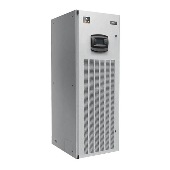
1 Product Overview Product Introduction The Liebert LPC series is the next generation series of air conditioners that provide precise environmental control. The Liebert LPC models are the latest in the long line of modern enterprise-grade products from the Liebert family. Incorporating the high standards associated with the Liebert name, the LPC series utilizes the latest technology, system components, and streamlined manufacturing process. -
Page 11: Model Description
The following section depicts the Model Description and various components that are an integral part of the air conditioner models in the Liebert LPC series. Further on, the working conditions and technical specifications will be discussed in the later sections. -
Page 12: Model Nomenclature
None SCR Heater Std. 1 Stage Air cooled-long piping>30m SCR Heater Opt. 2 Stage SFA Included Digit 14 Air Filter Digit 25 Order Identifier None Back Air Return Bottom Air Return SFA Included Vertiv I Liebert LPC I User Manual... -
Page 13: Components
1.4.1 Compressor The DC Inverter Scroll compressor (with variable frequency) used in the Liebert LPC series. The advanced compressor with a highly efficient motor and wide capacity regulation range is designed to deliver maximum cooling with low noise and significantly less vibration. Its expansive speed range and variable speed design imparts a new level of control for light load efficiency and dehumidification. -
Page 14: Electronic Expansion Valve (Eev)
Besides, the easy-to-connect facility bundled with the benefit of minimal wiring adds to the high performance with a greater range of possible airflow rates. Figure 1-5 shows the EC Fans used in the Liebert LPC model: Figure 1-5 EC Fan Vertiv I Liebert LPC I User Manual... -
Page 15: Infrared Humidifier
1.4.6 Electric Heaters The finned electric heaters used in the Liebert LPC series are highly reliable and extremely productive. Stainless steel is the material used for manufacturing these heaters with fin-tubular elements. The heaters perform at a quick pace and reduce the power requirement during mission-critical workflow. -
Page 16: Filter-Driers
Ministry of Information Enterprise, it ensures top reliability and maximum efficiency. An interesting development is the compatibility with Vertiv Co.’s remote monitoring-and- management application. SiteWeb (the remote management application) gathers a continuous stream of data related to vital health parameters such as DC Power, batteries, and renewable power sources to name a few. -
Page 17: Liquid Indicator
Table 2.1 ≤ 40 ℃ Ambient temperature L1015 LSF24-R3 > 40 ℃ LSF32-R3 For more information on the condenser, refer to the separate condenser manual which explains the entire condenser ecosystem in detail. Vertiv I Liebert LPC I User Manual... -
Page 18: Optional Components
SIC card with #77, #78 control panel is equipped with RS485 interface which is a standard protocol for the MODBUS. RDU-SIC can be equipped with monitoring cards, as shown in figure 1-10. The RJ45 interface is provided for customer access via USB port. Figure 1-10 Vertiv I Liebert LPC I User Manual... -
Page 19: Operating Parameters
Outdoor lowest outdoor operating temperature is -34°C. Protection Level IP20 <1000m. If the altitude is above 1000m, then Derating will Altitude occur. Please contact Vertiv™ for this resolution 380~415 (-10%~+6%)V,3N~50/60Hz Operating Voltage range Vertiv I Liebert LPC I User Manual... - Page 20 PART II INSTALLATION Vertiv I Liebert LPC I User Manual...
-
Page 21: Installation
One precaution is to choose roads that do not have too many bumps and if any, avoid it as much as possible. Liebert LPC series of air conditions are on the heavier side and therefore, it is recommended that equipment such as an electric forklift is utilized for these heavy-duty systems. Move the equipment to a location which is in the vicinity of the installation site. -
Page 22: Unpacking For Paper Packaging
The unit is fixed on a base pallet with M8 * 65 bolts. Use a 14mm wrench to remove • those bolts. Figure 2-4 shows the unit fixed on the base pallet using the M8 * 65 bolts. Vertiv I Liebert LPC I User Manual... -
Page 23: Unpacking For Wooden Packaging
In Figure 2-5, the tines of the forklift are inserted below the pallet. This is done to ensure that the equipment does not fall over leading to injury to the personnel or damage to the equipment. Vertiv I Liebert LPC I User Manual... -
Page 24: Removal Of External Package
Inspect and check all items for damage, either visible or concealed. Damage should be immediately reported to the carrier. A damage claim • needs to be filled and a copy of the same must be sent to Vertiv Co. or the authorized sales representative. 2.1.4 Removal of external package The chilled water version uses the international packaging. -
Page 25: Inspection
If any parts are missing or damaged, immediately report to the carrier about the same. If hidden damages are observed, then contact the local offices of that carrier as well as Vertiv Co. at the earliest. Vertiv I Liebert LPC I User Manual... -
Page 26: Installation Preparation
Take appropriate thermal insulation and antifreeze measures for outdoor water pipes to avoid poor drainage and insufficient water supply caused by freezing. Vertiv recommends that the site preparation is defined as per the requirements. However, if these requirements are not met, Vertiv recommends that rectifications be made on the site so that it complies with the specified requirements and conditions. -
Page 27: Mechanical Installation
Several factors such as pressure drop, compressor oil return, noise reduction, and • vibration are considered during the design and installation process. The units shall be fixed by screws and mounting rails to avoid vibrations during the start- • up or operating processes. Vertiv I Liebert LPC I User Manual... -
Page 28: System Arrangement During Installation
The following points should be taken into consideration before checking out the overall layout diagram: The single system is used as an example to describe the entire system. • Vertiv staff and qualified professionals lay out the piping in the laboratory. • Piping is done by technicians. •... -
Page 29: System Installation
Figure 2-13 depicts the schema of system installation when the condenser is • installed at a lower level than the compressor: Figure 2-13 The Condenser is lower than the Compressor during installation Vertiv I Liebert LPC I User Manual... -
Page 30: Product Dimensions
The Plenum is an assembly of all the components in the unit. The following table 2.2 displays the dimensions of a plenum: Table 2.2 Type Depth (mm) Width (mm) Height (mm) L1015 850 (D) 730 (W) 400 (600 optional) (H) Vertiv I Liebert LPC I User Manual... -
Page 31: Base Pallet Cut-Out Location Dimensions
Contact Vertiv Co. for non-standard production queries if the height of the platform selected for an air conditioning unit exceeds 600mm. 2.6.2 Base pallet cut-out location dimensions Following is a schematic diagram that depicts the cut-out location and dimensions of the base pallet. - Page 32 Hole for incoming water pipe of the humidifier D Hole for Drain pipe Figure 2-17 Side panel Knockout connection The equipment has knock-outs, be sure to mount the sleeve to the cable holes to avoid cutting the cables. Vertiv I Liebert LPC I User Manual...
-
Page 33: Installation Of The Indoor Unit
The base can be created by the users; alternatively, Vertiv Co. can be asked to create it too. Figure 2-18 depicts a schematic diagram of the production base along with the specific dimensions. -
Page 34: Installing The Condenser
Depending on the conditions for selecting the kit, the users shall decide whether there is a need for the extension kit while installing the pipes. All the joints of the cooling pipes must be silver-brazed. Vertiv I Liebert LPC I User Manual... -
Page 35: Connecting The Condensate Drain Pipe Of The Indoor Unit
100Kpa-700Kpa. • Also, when the main pipe pressure falls below 100Kpa, a water tank and pump system must be used. Vertiv I Liebert LPC I User Manual... -
Page 36: Connecting Copper Pipes Between The Indoor Unit And Condenser
• diameter of the indoor unit and outdoor unit should be determined according to specifications listed in the following table (Refer Table 2.6). • Alternatively, contact the technicians and engineers at Vertiv’s local office for the connection. Table 2.6 L1015 Pipe Length 12.7... - Page 37 If the length of the one-way pipe exceeds 30m or the vertical distance between the • indoor unit and outdoor unit exceeds the values in the table 2.7, consult Vertiv Co. for the installation. The recommended pipe sizes are equivalent lengths that consider the resistance of •...
- Page 38 0.44 0.24 1-1/8 0.56 A trap must be installed every 7.5m of the vertical distance. Please consult Vertiv Co. for inquiry and installation. • Vertiv Co. recommends the installation of the solenoid valve onto the outdoor project pipe of the ball valve on the liquid pipe to avoid the opening of the pipe during the installation of the pipe extension kit.
- Page 39 4. Finally, clip the coil of the valve body, press the coil tightly to ensure complete contact between the coil and valve body as displayed in Figure 2-24. Figure 2-24 Fixing the coil Vertiv I Liebert LPC I User Manual...
-
Page 40: Charging The Refrigerant And Adding The Refrigerant Oil
The added amount of POE oil of the Liebert LPC air conditioner is displayed in the table 2.11. L1015 use the POE oil. Therefore, contact Vertiv Co. if there is a requirement to add the refrigerant oil. -
Page 41: Removing Fastener & Vibration Absorbers
The fastening torque of the bolts is approximately (12 +/- 1) N-m. Refer to the Figure 2-25 in order to view the position of the L-shaped fixing plate on being fixed to the compressor base. Vertiv I Liebert LPC I User Manual... -
Page 42: Removal Of The Fastener Of Infrared Humidifier
Figure 2-26 Removal of the Fastener of infrared humidifier Before operating as a unit, remove the rubber string failing which the unit cannot detect the high water-level alarm. Do not touch the lamps with bare fingers. Vertiv I Liebert LPC I User Manual... -
Page 43: Inspection Of Mechanical Installation Checklist
The charged amount of refrigerants and lubricants has been roughly calculated The unit must have a plenum or air supply pipe connection; Furthermore, the fan as well as the heater must not be accessible after the installation Vertiv I Liebert LPC I User Manual... -
Page 44: Electrical Installation
• TN and TT type star connections to the power distribution systems are used. If any other type of connection is required, please call the support number for Vertiv Co. • Use a breaking device in order to get disconnected from the power supply. -
Page 45: Connecting The Power Cable Of The Indoor Unit
Connect the terminals L1, L2, and L3, N, PE respectively to the corresponding counterparts of the external power supply. Fix the cable to the cable clamp located at the inner side panel of the unit. The cable sizes should meet the local wiring regulations. Vertiv I Liebert LPC I User Manual... -
Page 46: Remote Temperature & Humidity Sensor Placement
• Vertiv recommends that the sensors be installed in the test area of the application site. Ensure that the installation location is not affected by Heat dissipation. Another aspect is that the installation location must be as far as possible from the •... - Page 47 • Figure 2-31 shows multiple sensors connected in a series: Figure 2-31 Chain connection of sensors in a series Vertiv I Liebert LPC I User Manual...
-
Page 48: Connecting The Water-Under- Floor Sensor
When the contact is open, the external alarm doesn’t get generated. When the contact gets closed, the external alarm is generated. In this case, the input state of the customer terminal Vertiv I Liebert LPC I User Manual... - Page 49 In the case of a SIC card, the customer needs to connect #A, #B, #GND and #12 on the SIC card to #77, #78, #GND and #12V respectively on the terminal block. Vertiv I Liebert LPC I User Manual...
-
Page 50: Connecting The Solenoid Valve Of The Pipe Extension Kit (Optional)
A signal line required when the compressor enters the condenser through the external electric power line box waterproof connector, the inner diameter of the joint is φ6mm. Vertiv I Liebert LPC I User Manual... - Page 51 The control cables are well connected All the cables connections are fastened and screws fitted correctly Do not switch the power on as Vertiv Co. authorized professional technicians have to perform a check and confirm whether it is good to go. The commissioning process will be performed by the Vertiv Co.
-
Page 52: Pre-Commissioning Checklist
Copper pipes are painted with the proper color code Additional piping kit installed in case of a vertical distance between indoor to outdoor is more than 20RMT (or equivalent length exceed 30 Rmt) Vertiv I Liebert LPC I User Manual... - Page 53 Isolating valve provided on the inlet of humidifier piping Fresh water head pressure maintained of 21 - 100 PSI & with PPM level of 80 to 300 (optional) Ensure no leakage in the humidifier & drain piping before commissioning Vertiv I Liebert LPC I User Manual...
-
Page 54: Commissioning
If evacuation mode is not getting activated, the background service tooling menu needs to be checked to ensure that the line solenoid valve and electronic expansion valve in an open state along with high and low pressure setting of the needle deactivated simultaneously to Vertiv I Liebert LPC I User Manual... -
Page 55: Adding Refrigerant Oil
℃ LSF24 LSF32 Outdoor Model Outdoor temperature Standard filling amount (Unit: kg) Note: The standard refers to an amount of charge indoor outdoor + charge amount to suit a piping length upto 10m. Vertiv I Liebert LPC I User Manual... -
Page 56: Troubleshooting
#78, open the software and select the corresponding communication parameters. Serial number and computer equipment manager matches the COM port, baud rate consistent with the device (device default 19200), as shown in Figure 3-2. Figure 3-2 LPC services software communication parameters Vertiv I Liebert LPC I User Manual... -
Page 57: Start-Up Guide
Use a debug function key, the function to fix the output for easy debugging and testing. Figure 3-4 Key service software debugging button Vertiv I Liebert LPC I User Manual... -
Page 58: Commissioning Steps
On closing the electric heating breaker, change set-point temperature on the controller. This will start the electric heater (or manual start) and then check each phase current to ensure the electrical heating function is on. Vertiv I Liebert LPC I User Manual... -
Page 59: Detecting The Humidifier
Compound pressure gauge valve fully closed, manually start the compressor operation (output of the compressor 76%), when the system is operating normally, the low pressure valve to maintain a small opening degree, reduce the risk of damage to the compressor. Vertiv I Liebert LPC I User Manual... -
Page 60: Inspection After Completion
4. Check the drainage unit is smooth, condensate drain connections for leaks. 5. Check the compressor intake and exhaust port is loose, whether there is oil leakage. 6. Recording parameters fill in commissioning report and submit it to the customer. Vertiv I Liebert LPC I User Manual... - Page 61 PART III SYSTEM OPERATION & GENERAL MAINTENANCE Vertiv I Liebert LPC I User Manual...
-
Page 62: Controller
Press this key to scroll downwards on multi-screen displays • Press this key to move to the next menu Enter • Press this key to save the settings after change in the parameters or values Vertiv I Liebert LPC I User Manual... -
Page 63: Indicators
(such as fan, cooling, and on/off standby mode). The main interface consists of three modes related to the operation of the unit, namely- Dynamic Running state icons • • Locking state icons • On/Off/Standby state icons Vertiv I Liebert LPC I User Manual... - Page 64 – Standby Unit Shutdown • Remote Shutdown • Unit Shutdown • Figure 4-3 shows the 3 shutdown controller modes based on the shutdown state of the air conditioner: Figure 4-3 Shutdown interface Vertiv I Liebert LPC I User Manual...
-
Page 65: Main Menu
Up/Down key to scroll the cursor. Select the required sub-menu. Press Enter to gain access to the second level sub-menu. • The Main Menu contains 7 sub-menus, divided into 2 displays as depicted in Figure 4-5. Vertiv I Liebert LPC I User Manual... -
Page 66: Setting Parameters For The Sub-Menu
Press the Up or Down key to select the required parameter. • On selecting the parameter, Press the Enter key to confirm and validate the • parameter. • Press the ESC key to move back to the higher-level menu. Vertiv I Liebert LPC I User Manual... -
Page 67: User Menu
Query the input power and frequency of the power Communication settings Set the communication, address and baud rate Main Menu --> System Time settings Set the time Settings Password settings Setting a password Vertiv I Liebert LPC I User Manual... - Page 68 Time (Alarm Start and End Time) The controller can store up to 100 Alarm Status records at a given point of time. Alarm statuses will be automatically cleared in case of a power failure. Vertiv I Liebert LPC I User Manual...
- Page 69 500 history alarms and these records will remain intact even in the case of a power failure. 4.6.4 Alarm Setup The Alarm Setup function contains set points that define the configuration of the system. Figure 4-9 shows the Alarm Settings interface: Figure 4-9 Alarm Setup Vertiv I Liebert LPC I User Manual...
- Page 70 Press the Enter key to explore the sub-menu of the Set Point Control Interface. • The options in the sub-menu are used to set the temperature, humidity, and altitude of the operational unit. Figure 4-11 shows the interface of the Temperature and Humidity settings menu: Vertiv I Liebert LPC I User Manual...
- Page 71 The System Status can be viewed in the Main Menu (1/2) screen. Figure 4-12 System Status Press the Enter key, following which the unit temperature and humidity sensors can be calibrated. Even the power status parameters can be queried. Vertiv I Liebert LPC I User Manual...
- Page 72 Figure 4-14 Power Status The Power Status menu is used to browse and view the input power status of the air conditioner such as the A-Phase voltage, B-Phase voltage, C-Phase Voltage, and Power Frequency. Vertiv I Liebert LPC I User Manual...
- Page 73 Press Enter to view the sub-menu of the System Settings menu item. • It contains 3 settings, namely – Monitor Setup • Time/Date Setup • Password Setup • 4.6.11 Monitoring Setup Figure 4-16 shows the Monitoring Setup menu: Figure 4-16 Monitoring Setup menu Vertiv I Liebert LPC I User Manual...
- Page 74 Figure 4-17 Time/Date setup Set the time and date using these specific settings. 4.6.13 Password Setup Figure 4-18 shows the Password settings screen: Figure 4-18 Password Setup Passwords can be setup and modified using this function. Vertiv I Liebert LPC I User Manual...
-
Page 75: Display Setup
Press Enter and on accessing the Run Hours screen, the total run hours of a fan, compressor, heater, humidifier, and the Cumulative run time can be browsed. Figure 4-20 shows the Run Hours sub-menu: Figure 4-20 Run Hours Vertiv I Liebert LPC I User Manual... -
Page 76: Temperature And Humidity Graph
Enter key to enter the editing mode and zoom in or zoom out the graph using the Up and Down key. Figure 4-22 Temperature Graph Back to the Temperature and Humidity Graph menu interface, choose the Hum Graph menu. Vertiv I Liebert LPC I User Manual... - Page 77 The following is a brief overview of the Remote Monitoring Mode: The Liebert LPC humidity air conditioners support the multiple monitoring modes: Connecting the RDU and SiteWeb - A monitoring system developed by Vertiv Co. • Alternatively, A third-party monitoring system can be used in compliance with the standard protocol of the Ministry of Industry and Information technology.
-
Page 78: General Maintenance
Qualified and Professional Maintenance personnel are the ones supposed to operate and handle the equipment. Careful and cautionary measures are conveyed to the professional personnel and therefore, only these personnel may perform maintenance on these machines. Vertiv I Liebert LPC I User Manual... -
Page 79: Routine Monthly Inspection
Check and fix connectors Check the functioning of electrical heating Check water pan drainage for clogging Check the Humidifier Lamp Infrared Humidifier Check and fix connectors Check the water pan for mineral deposits Vertiv I Liebert LPC I User Manual... -
Page 80: Routine Bi-Annual Inspection
Check the Humidifier Lamp Check the water pan for mineral deposits Infrared Humidifier Check and fix connectors Check Fuses, Circuit breakers, and MCBs Electric Control Check Control Program section Check the closing condition of the contactor Vertiv I Liebert LPC I User Manual... -
Page 81: Inspection Of Electrical Connections
Check the output connections between the control interface board, and various contactors and solenoid valves for the liquid pipes. Inspect the input connection between the control interface board and fan overload protector, high pressure switch, Vertiv I Liebert LPC I User Manual... -
Page 82: Filter Maintenance
Ensure that the unit is powered off while replacing the filter. • After the filter is replaced, the fan speed reading must be cleared and set to 0. • Vertiv I Liebert LPC I User Manual... -
Page 83: Infrared Humidifier
While two of the switches are automatic reset ones, the remaining one is a manual reset switch. Figure 5-1 shows a schematic representation of the three switches inside an electric heater: Figure 5-1 Fin-tube type electric heater Vertiv I Liebert LPC I User Manual... -
Page 84: Drainage Check
When inspecting the drainage, check if there are no unwanted substances, debris, alien objects, or particles in the water pan. Check the drainage for leakage too. The check has to be conducted periodically on a regular basis. Vertiv I Liebert LPC I User Manual... -
Page 85: Appendix
6 Appendix 6.1 Circuit Diagram Refer the attached drawing. - Page 86 1. ALL FIELD WIRING TO BE PER LOCAL CODES. USE COPPER CONDUCTORS ONLY. FACTORY MOUNTED MAIN UNIT SWITCH 2. SEE INSTALLATION AND USER MANUAL(S). SEE UNIT NAMEPLATE 3. JUMPER TO BE REMOVED WHEN OPTIONAL COMPONENT IS USED. FOR MAIN SUPPLY LINE WIRE SIZING VOLTAGE...
Need help?
Do you have a question about the Liebert LPC Series and is the answer not in the manual?
Questions and answers