Table of Contents
Advertisement
Advertisement
Table of Contents

Related Manuals for Vertiv Liebert CRV Plus


Summary of Contents for Vertiv Liebert CRV Plus
- Page 1 Liebert CRV+ Precision Air Conditioner User Manual...
- Page 3 Vertiv Co., Ltd. China • Website: www.vertivco.com E-mail: support@Vertivco.com Customer service hotline: 4008876510 Asia Pacific • Homepage: www.vertivco.com. E-mail: overseas.support@Vertivco.com For Technical Support, users may contact the nearest Vertiv Co. local sales office or service center.
- Page 4 Purpose of the Document This document applies to the Liebert CRV+ series of precision air conditioners and cooling solutions which maintain an optimal environmental control mainly for testing laboratories, data center rooms and similar technological ecosystems at minimal operating costs. This document explains the product description, installation measures, operational workflow, maintenance, and detailed aspects from the user perspective.
- Page 5 Safety Precautions & Measures The important safety precautions and measures that should be followed during the installation and maintenance of the Liebert CRV+ models are described in the following sections. Read the manual prior to installation and operation of the unit. Only qualified personnel should move, install, or service this equipment.
- Page 6 Therefore, care should be taken to ensure that the unit must not be located directly above any equipment that could sustain damage due to water and excessive moisture. Using a leak detection system for unit and system supply lines are recommended by Vertiv Co.
-
Page 7: Table Of Contents
TABLE OF CONTENTS Chapter 1 Introduction ......................1 1.1 Model Nomenclature ........................2 1.2 Basic Performance Parameters....................2 1.3 Product Description ........................3 1.3.1 DC Brushless Compressor......................... 4 1.3.2 Fan ............................... 5 1.3.3 Evaporator ............................5 1.3.4 Electronic Expansion Valve (EEV) ....................6 1.3.5 Electrode Humidifier ......................... - Page 8 2.4 Electrical Installation........................37 2.4.1 On-site Wire connections ....................... 37 2.4.2 Installation Notes ..........................37 2.4.3 Connecting cables of the Indoor unit ................... 38 2.5 Commissioning Overview ....................... 43 2.5.1 Self Check ............................43 2.5.2 Preparations for Startup ........................ 44 2.5.3 Startup Inspection .......................... 46 Chapter 3 System Operation &...
- Page 9 PART I GENERAL INFORMATION...
-
Page 11: Chapter 1 Introduction
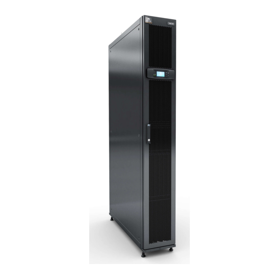
It is a top-notch system that adheres to the standard in Precision Air Cooling in terms of energy-efficiency, space requirements, and reliability. Figure 1-1 shows the appearance of various models in the Liebert CRV+ series: Figure 1-1 Models in the CRV+ series Vertiv | Liebert CRV+ | User Manual... -
Page 12: Model Nomenclature
The basic performance parameters of the Liebert CRV+ AC series are given in Table within Listing 1.1. Listing 1.1 Nominal cooling Power Heating capacity Humidification Model capacity (kW) (kW) (kW) capacity (kg/h) CR012 13.6 CR025 20.8 CR035 38.1 10.1 Condition: Return air 37˚C, 24%RH & 45˚C condensing temperature Vertiv | Liebert CRV+ | User Manual... -
Page 13: Product Description
Liebert CRV+ is designed to comply with mission-critical requirements and ensure that servers are maintained at the correct temperature and humidity levels. Figure 1-3 shows the various components and their respective locations: Figure 1-3 Components and their locations Vertiv | Liebert CRV+ | User Manual... -
Page 14: Dc Brushless Compressor
CRV+ series. Figure 1-4 shows the image of a DC brushless compressor: Figure 1-4 DC Brushless compressor Vertiv | Liebert CRV+ | User Manual... -
Page 15: Fan
Streamlined Heat exchanger design and air distribution for optimum performance Fin-tube heat exchanger for higher efficiency Figure 1-6 shows the image of an Evaporator: Figure 1-6 Evaporator Vertiv | Liebert CRV+ | User Manual... -
Page 16: Electronic Expansion Valve (Eev)
1.3.5 Electrode Humidifier The Electrode humidifier helps to maintain constant humidity in test chambers and is quite efficient in small-and medium-load applications. Figure 1-8 depicts the image of an Electrode Humidifier: Figure 1-8 Electrode Humidifier Vertiv | Liebert CRV+ | User Manual... -
Page 17: Electric Heater
Self-recovery upon power failure, high-voltage & low-voltage protection Phase loss protection Automatic phase-sequence switching upon the anti - phase and rotate speed control of the outdoor fan High-end Fault diagnostic system to facilitate easy equipment maintenance Vertiv | Liebert CRV+ | User Manual... -
Page 18: Condenser
An interesting development is the compatibility with the Liebert CRV+ series models with the Modbus protocol. Through the configured RS 485 port or TCP/IP port, the CRV+ systems can communicate with the host computer in addition to remotely taking charge of the host software. Vertiv | Liebert CRV+ | User Manual... -
Page 19: Working Conditions
-34°C Protection level (indoor unit) IP20 Altitude < 1000m. Above that, please contact Vertiv Co. Operation voltage range (380 ~ 415)V ± 10%, 3N ~ 50Hz / 60Hz 1.5.2 Storage Environment The following table in Listing 1.4 defines the Storage Environment parameters including the ambient humidity, ambient temperature, and storage time conditions. -
Page 20: Refrigerant Charging Requirement
Low quality or counterfeit refrigerant will damage the system drastically. Use the refrigerant approved by Vertiv Co., Ltd. to avoid the system abnormality or damage caused by using other brands of refrigerant. Listing 1.5 depicts the refrigerant brands, which are approved by Vertiv Co. Ltd. - Page 21 Part II INSTALLATION Vertiv | Liebert CRV+ | User Manual...
-
Page 22: Chapter 2 Installation
Figure 2-1 Moving the equipment using a Forklift truck Vertiv | Liebert CRV+ | User Manual... -
Page 23: Unpacking
Initially, remove the top cover and winding stretch film. Next, remove the honeycomb cardboard as depicted in Figure 2-3. Figure 2-3 Unpacking the outer package Vertiv | Liebert CRV+ | User Manual... -
Page 24: Inspection
If any parts or components are missing or damaged, immediately report to the carrier about the same. If hidden damages are observed, then contact the local offices of that carrier as well as Vertiv Co. at the earliest. -
Page 25: Installation Space Requirements
Figure 2-5 depicts the space allocated for servicing and maintenance. Figure 2-5 CRV+ maintenance space Vertiv Co Contact the . team for special applications, which would need some modifications to work at an optimal level. Vertiv | Liebert CRV+ | User Manual... -
Page 26: Installation Tools
Ensure that the tools used in the installation, operation, and maintenance processes are insulated. This safety measure is important for professionals and service personnel who work with this CRV+ range air conditioner. Vertiv | Liebert CRV+ | User Manual... -
Page 27: Mechanical Installation
Follow the design drawings strictly when installing the equipment. Reserve space as per the maintenance and serviceability instructions in the previous chapter on Installation Preparation. The manufacturer’s engineering dimension drawings must be taken as a reference while installing the equipment. Vertiv | Liebert CRV+ | User Manual... -
Page 28: System Arrangement During Installation
Vertiv staff and qualified professionals lay out the piping in the laboratory. Piping is done by technicians. Components (marked with *) are not supplied by Vertiv Co. but are recommended for proper circuit operation and maintenance. Additional components (marked with +) are required when the equivalent length exceeds 30m. -
Page 29: System Installation Mode
However, if the condenser is installed lower than the compressor, then there is no modification required as it fits the bill perfectly. Vertiv | Liebert CRV+ | User Manual... -
Page 30: Product Dimensions
Figure 2-8 The Condenser is lower than the Compressor during installation 2.3.3 Product Dimensions The dimensions and weight of the indoor unit are displayed in Figure 2-9 and in the table within Listing 2.2. Figure 2-9 Dimensions of an indoor unit Vertiv | Liebert CRV+ | User Manual... - Page 31 The locations of the pipe inlets and outlets on the unit base plate are shown in Figure 2-10: Figure 2-10 Base Plate Location for pipe outlets The following table in Listing 2.3 depicts the dimensions of the base plate pipe outlet: Listing 2.3 Model CR012 CR025 CR035 Vertiv | Liebert CRV+ | User Manual...
- Page 32 The location and dimensions of the air outlet at the front are shown in Figure 2-12: Figure 2-12 Front air outlet locations & dimensions (unit: mm) To prevent damage of the power cable, the cable entry hole is fitted with brushing for protection. Vertiv | Liebert CRV+ | User Manual...
-
Page 33: Installation Procedures
Screw down the fixing nuts on the feet bolts counter-clockwise and the leveling gets completed. If the machine room has a mounting bracket, and its width does not exceed 30mm, remove the feet and fix the cabinet onto the mounting bracket. Vertiv | Liebert CRV+ | User Manual... - Page 34 Install bolts in the four holes at the bottom to fix the cabinet onto the floor bracket of the machine room. Install bolts in the four holes at the top to fix the cabinet to connect the cabinet with the top bracket of the machine room. Vertiv | Liebert CRV+ | User Manual...
- Page 35 (side of the hinge) and rack frame adjacent to the cabinet as depicted in Figure 2-16. Mounting screw GB819_1_2000_M5x12 Cabinet connector A amplified Figure 2-16 Schematic diagram for connecting the cabinet Install the other 6 cabinet connectors based on the same method. Vertiv | Liebert CRV+ | User Manual...
-
Page 36: Piping
Use the same method to remove the bottom filter. Figure 2-17 depicts the process of removing the filters: Mounting screw GB9074_4_88_M4x12 Fixing flake of the filter A amplified Figure 2-17 Removing the Filters Vertiv | Liebert CRV+ | User Manual... - Page 37 Allow a tilt of 2% towards the direction of the drainage flow. The trap is mandatory and should be located 30 cm below the water tray. The tray must be kept under the movable floor. Figure 2-18 Process of draining the Condensate water Vertiv | Liebert CRV+ | User Manual...
- Page 38 The pressure range of the main pipe should be in the range of 100kPa – 700kPa. In some cases, the process needs to be in compliance with the local laws and regulations resulting in the introduction of some other components. Vertiv | Liebert CRV+ | User Manual...
- Page 39 Listing 2.5. Alternatively, contact the Vertiv support office to seek the help of the technician for gauging the length and diameter. Listing 2.5...
- Page 40 POE refrigeration oil being affected with damp. It may result in an adverse effect on the life of the key components and the stability of the system operation. Vertiv | Liebert CRV+ | User Manual...
- Page 41 0.24 1-1/8 0.56 A trap must be installed every 7.5m of the vertical distance. Please consult Vertiv for such specific inquiry and installation. There is no necessity of cutting the indoor unit pipes while installing the solenoid valve. After the entire system is installed, open the ball valve to keep the pressure and carry out the vacuum...
- Page 42 Charging Refrigerant and Adding Refrigeration Oil The Liebert CRV+ air conditioners come pre-charged in the factory with 2Bar Nitrogen. The table in Listing 2.7 indicates the standard charged amount. The users can determine the charging amount of the Vertiv | Liebert CRV+ | User Manual...
- Page 43 The refilled refrigerant will dilute the POE oil in the system and plays a major role in the lubrication and cooling effects of the POE oil. Thus, it is for this purpose that the refrigerant oil must be added. Vertiv | Liebert CRV+ | User Manual...
-
Page 44: Removing Transportation Fastener And Vibration Absorber
Refrigeration oil charging is not needed Consult Vertiv Co. for adding the refrigeration oil Do not use poor quality refrigeration oil as it can damage the system Select the right make and type of refrigeration oil depending on the model. - Page 45 Use M13.5 rubber plugs to seal four holes at the top of the cabinet and M12*30 bolts to seal 8 holes at the top plate of the cabinet. This prevents water from entering the cabinet. Vertiv | Liebert CRV+ | User Manual...
-
Page 46: Checklist For Completed Mechanical Installation
All pipe connectors are tight The fasteners used for transportation have been removed After installation, foreign materials in and around the equipment are removed (such as shipping materials, construction materials, tools, and so on) Vertiv | Liebert CRV+ | User Manual... -
Page 47: Electrical Installation
For the air conditioner configured with EC fans, the unit power grid adheres to the TN or TT star connection power distribution system. However, if there is a need to configure another type of power grid, contact the Vertivsupport team for the same. Vertiv | Liebert CRV+ | User Manual... -
Page 48: Connecting Cables Of The Indoor Unit
2-28. For detailed layout information on low voltage components, refer to the labels pasted on the cabinets and units. Figure 2-28 Unit electrical control box and cable connection (open the back door 120°) Listing 2.11 MCB current Model Current(A) CR012 NDM1-63C32/3 CR025 NDM1-63C40/3 CR035 NDM1-63C50/3 Vertiv | Liebert CRV+ | User Manual... - Page 49 Standard model with Standard model with Model model with electric model electric humidifier heater & heater humidifier CR012HA1380S02E10000PV000 19.1 19.1 CR012RA1380S12E10000PV000 19.1 CR025HA1380S02E10000PV000 24.9 24.9 CR025RA138SS12E10000PV000 CR035HA1380S02E10000PV000 31.6 46.6 42.3 46.6 CR035RA138SS12E10000PV000 46.6 Vertiv | Liebert CRV+ | User Manual...
- Page 50 If a SIC card is equipped, connect A#, B#, GND#, and 12# on the SIC card to the respective counterparts on the terminal block. Refer to Appendix 1 Circuit Diagram for in-depth information. Vertiv | Liebert CRV+ | User Manual...
- Page 51 Rack temperature sensor IRM-S01 address settings are depicted in the table in Listing 2.13. Listing 2.13 Sensor Rack temperature 1 Rack temperature 2 ON — “1”; OFF — “0” Rack temperature 3 Rack temperature 4 Vertiv | Liebert CRV+ | User Manual...
- Page 52 For more specific connecting points on the interface board, refer to the connecting terminal number of the liquid route solenoid valve depicted in the Circuit Diagram in the Appendix-1 section. Vertiv | Liebert CRV+ | User Manual...
-
Page 53: Commissioning Overview
All the wiring and connector connections, including the fixing blocks are fixed firmly and appropriately. Do not power on or operate the installed unit as Vertiv's authorized professional technicians have to perform a check and confirm whether it is good to go. Starting up and Operating the unit should only commence if the commissioning process is successful, following which Vertiv’s engineers give the go-ahead... -
Page 54: Preparations For Startup
Vertiv's engineers and personnel need to perform the check-up as per the table in Listing 2.15. Listing 2.15 Items Inspection contents Results Room Thermal isolation, moisture proof and sealing performances of environment protective structure Whether the fixing is reliable and whether the vibration proof pad... - Page 55 Check the electric circuits: Fasten all the electrical connections, and make sure that there is no short circuit and open circuit and the insulation is good; Check the main power supply voltage of the unit. Vertiv | Liebert CRV+ | User Manual...
-
Page 56: Startup Inspection
℃. The suction pressure is 8-10kg, discharge pressure is 21-23kg, and the superheat is more than 12 ℃. For the low temperature liquid storage system, be sure to operate according to relevant instruction files. Vertiv | Liebert CRV+ | User Manual... - Page 57 In order to ensure the reliability of the compressor, avoid directly turning off the circuit breaker of the compressor. Refer to the Refrigerant refill and charging section in the user manual for the calculations. Vertiv | Liebert CRV+ | User Manual...
- Page 58 Once the commissioning is completed, the Vertiv engineers will confirm the same using the checklist in Listing 2.16 Listing 2.16 Check item Result Check and confirm that all the output functions are automatic Check that the Temperature & Humidity settings as well as the control...
- Page 59 PART III SYSTEM OPERATION & GENERAL MAINTENANCE Vertiv | Liebert CRV+ | User Manual...
-
Page 60: Chapter 3 System Operation & General Maintenance
Control button Function descriptions ON/OFF button Press this button for 3s to turn on or turn off the AC unit Enter button (ENT) Enter the selected menu screen. Validate the parameter setting value Vertiv | Liebert CRV+ | User Manual... -
Page 61: Common Operational Function Examples
Press the Enter button to highlight the parameter field of Hi Sup Temp. In order to select the parameter option, scroll using the UP and Down buttons. Select/change the specific Parameter. Vertiv | Liebert CRV+ | User Manual... -
Page 62: Main Screen
Dehumidifying state. Displaying 100% in dehumidifying mode, otherwise, displaying 0% Unit property/operation status. S: single; T: teamwork; ON: running; R-OFF: remote shutdown; L-OFF: local shutdown; M-OFF: monitoring shutdown; MANU: manual mode; BKUP: backup; Lock: lock Vertiv | Liebert CRV+ | User Manual... -
Page 63: Password Interface
3.1.6 Menu Structure In this section, the different kinds of menu and sub-menu options will be discussed to help users get a grip on the Controller functions. Vertiv | Liebert CRV+ | User Manual... - Page 64 Alarm Menu On the Main Menu screen, click on the Alarm Menu to gain access to the Alarm Menu interface. Press the Up and Down button to scroll up or down the menu items. Vertiv | Liebert CRV+ | User Manual...
- Page 65 The Alarm History menu is used to view the historical alarm records of the AC unit. It also displays the Alarm type, Alarm Start time and Alarm End time. Figure 3-8 depicts the Alarm History screen: Alm Hist HP Alarm 2012/01/01 00:00 2012/01/01 00:02 Figure 3-8 Alarm History menu Vertiv | Liebert CRV+ | User Manual...
- Page 66 Settings menu as depicted in Figure 3-10. Figure 3-10 Alarm Setting menu Press the UP and Down to scroll through the menu. The Alarm Set settings will not be lost despite a power failure. Vertiv | Liebert CRV+ | User Manual...
- Page 67 Select the System Alarm item on the Alarm Set screen to enter the screen as depicted in Figure 3-12. Press the Up or Down button to scroll through the menus. Figure 3-12 System Alarm Menu Vertiv | Liebert CRV+ | User Manual...
- Page 68 Select the Sensor Alarm item on the Alarm Set screen to access the menu. Press the Up and Down button to scroll through the menu items in the Sensor Alarm menu. Figure 3-13 depicts the Sensor Alarm menu items. Figure 3-13 Sensor Alarm Vertiv | Liebert CRV+ | User Manual...
- Page 69 Figure 3-15 depicts the EEV Alarm menu: Figure 3-15 EEV Alarm The EEV Alarms are crucial fault alarms, which cannot be set to OFF; however, they can be set to ENA and DISA. Vertiv | Liebert CRV+ | User Manual...
- Page 70 SUP is selected for Comp mode. When REM is selected as the Comp mode, the temperature is set through Ret Stpt; When REM is selected as the Comp Mode, the temperature settings are set through the REM Stpt. Vertiv | Liebert CRV+ | User Manual...
- Page 71 EEV. Figure 3-19 depicts the Run State displaying the running state of the compressor, fan and EEV: Figure 3-19 Run State Vertiv | Liebert CRV+ | User Manual...
- Page 72 After going through the menu, the current input and output states of the devices can be viewed using the Switch Signals utility. Figure 3-21 shows the screen for the Switch Signals function: Figure 3-21 Switch Signals Vertiv | Liebert CRV+ | User Manual...
- Page 73 XX is the serial number of the start and stop record while YY is the total number of start and stop records. Figure 3-24 depicts the records of the fan component. Figure 3-24 Fan records Vertiv | Liebert CRV+ | User Manual...
- Page 74 On selecting Yes, all the system settings will be reset to the original factory values. However, the Run Time or Historical Alarm data will not be cleared. Use the Reset Factory option with caution as it can clear all user settings and shut down the unit. Vertiv | Liebert CRV+ | User Manual...
- Page 75 Fan 1 State – Fan 4 State are read-only values. On selecting 35 kW, only the Fan 1 State and Fan 2 State will be displayed. Comp Set The Comp Set screen is depicted in Figure 3-28. Figure 3-28 Comp Set items Vertiv | Liebert CRV+ | User Manual...
- Page 76 Some parameters such as Soft Off and Lquid Valve cannot be set as they are read—only attributes. Exiting the manual mode has to be done manually. Preferably, only qualified personnel or trained professionals should be allowed to use the system in Manual Mode. Vertiv | Liebert CRV+ | User Manual...
- Page 77 Figure 3-32 depicts the Help Menu screen: Figure 3-32 Help Menu In Figure 3-32, all the options are functional, except for the Enab 1st Run which cannot be even viewed by the users. Vertiv | Liebert CRV+ | User Manual...
- Page 78 The Password settings will not be lost in case of a power failure. Figure 3-34 depicts the Password menu: Figure 3-34 Password Menu screen Version Info This facility is used to view the software version as depicted in Figure 3-35: Figure 3-35 Version Info Vertiv | Liebert CRV+ | User Manual...
-
Page 79: General Maintenance
Following is a checklist which contains parts and components that are to be checked to ensure proper and accurate functionality. In addition to that, there may be wear and tear of the equipment. Vertiv | Liebert CRV+ | User Manual... -
Page 80: Routine Maintenance And Inspection (Half -Yearly)
Air-cooled The fan vibration absorber is not deteriorated or damaged condenser (if used) The SPD board should be effective (in the seasons, when the storms are common, the SPD board should be checked Vertiv | Liebert CRV+ | User Manual... -
Page 81: Self-Diagnosing Functions
Fasten all the electrical connection terminals Check that the sockets and plugs are in good condition. Replace the contactors, if required. If the power cables are damaged, get them replaced by a qualified/certified electrician. Vertiv | Liebert CRV+ | User Manual... - Page 82 Simulate and inspect the operation-and-working states of protecting units such as high/low pressure alarm, high/low temperature alarm, high water level alarm, and over-temperature alarm and over-temperature protection. Check the sensors. Vertiv | Liebert CRV+ | User Manual...
-
Page 83: Air Filter Maintenance
Cut off the power before replacing the filter. Clear the fan operating time after replacing the filter. Vertiv | Liebert CRV+ | User Manual... -
Page 84: Fan Kit Maintenance
If the heating is not effective, the electric heater needs to be replaced. For replacement, contact the maintenance personnel and support team of Vertiv. 3.2.8 Refrigerating System Maintenance Following are the basic instructions relevant to the maintenance of the Refrigerating system: Check the refrigerating system once a month to ensure the system functionality. -
Page 85: Troubleshooting
If the motor is too hot, cut off the fan power; after the motor cools down, power on it again for recovery. In the event of a hall failure, factory service is required to fix the issue. Vertiv | Liebert CRV+ | User Manual... - Page 86 The Compressor internal circuit. In such a scenario, wait till the coil is closed, and the protector is open cooled following which it will be restored compressor does automatically not start Vertiv | Liebert CRV+ | User Manual...
- Page 87 Low condensing pressure Check whether the condenser is faulty Refer to the handling methods of ”Low suction Liquid returned pressure” or ”liquid returned” Compressor too noisy Bearing worn out due to Add lubricant lubricant loss Vertiv | Liebert CRV+ | User Manual...
- Page 88 Too high compression ratio Compressor over- Check that the fans of the evaporator and temperature condenser are normal Too high suction overheat Regulate the EEV or add proper amount of degree refrigerant Vertiv | Liebert CRV+ | User Manual...
-
Page 89: Appendix 1 - Circuit Diagrams
Wire color code: Ethernet or CAN wiring BK-Black P-Purple Factory supplied 24 volt wiring BL-Blue R-Red Device own line YE-Yellow BR-Brown Inline quick disconnect WH-White GR-Grey Terminal block connector Naked crimping connector Y/GN-Yellow green Vertiv | Liebert CRV+ | User Manual... - Page 90 Wire color code: Ethernet or CAN wiring BK-Black P-Purple Factory supplied 24 volt wiring BL-Blue R-Red Device own line BR-Brown YE-Yellow Inline quick disconnect WH-White GR-Grey Terminal block connector Y/GN-Yellow green Naked crimping connector Vertiv | Liebert CRV+ | User Manual...
- Page 91 配线色标/Wire color code: Ethernet or CAN wiring/以太网或CAN线路 BK-Black/黑色 P-Purple/紫色 Factory supplied 24 volt wiring/出厂24V线路 BL-Blue/蓝色 R-Red/红色 Device own line/器件自带线 BR-Brown/棕色 YE-Yellow/黄色 Inline quick disconnect/线上快速对插端子 WH-White/白色 GR-Grey/灰色 Terminal block connector/线缆端子 Y/GN-Yellow green/黄绿色 Naked crimping connector/裸压端子 Vertiv | Liebert CRV+ | User Manual...
-
Page 92: Appendix 2 - Micro-Processing Controller Menu Structure
Power PL Phase C R.T9 Cal LP Sen Lock Frequency Temp10 Water OF DIP Switch R.T10 Cal Water UF Fan Alm Heat Alm Hum Alm Filt Clog Filt Maint Remote Addr Overlap Loss Master Vertiv | Liebert CRV+ | User Manual... - Page 93 Phase C R.T9 Cal Fan4Freq Freq Offset Frequency LP Sen Temp10 Lock DIP Switch R.T10 Cal Water OF Water UF Fan Alm Heat Alm Filt Clog Filt Maint Remote Addr Overlap Loss Master Vertiv | Liebert CRV+ | User Manual...
-
Page 94: Appendix 3 - Alarm Control Menu Table
Ret Hum Sensor Alarm Hi HS Temp Hi Exh Lock Air Temp Sensor Alarm Comp OC Lo Exh Lock Sup Temp Sensor Alarm Comp PL Power Lost Rem Temp Sensor Alarm BV Abnor Vertiv | Liebert CRV+ | User Manual... -
Page 95: Appendix 4 - Hazardous Substances Or Elements Declaration
APPENDIX 4 - Hazardous Substances or Elements Declaration Vertiv | Liebert CRV+ | User Manual... -
Page 96: Appendix 5 - Troubleshooting Of Common Startup Faults
Check the 220VAC control voltage between A1 available, but close: Failure of control board and A2 of the contactor, and check if the J18-1 the Electric and contactor, or poor and 4 of the control board outputs 220V. Vertiv | Liebert CRV+ | User Manual... - Page 97 Check if the water level switch (or short circuit J21-5, 6) can make KA1 close, and check if the pump power module has 220V voltage Vertiv | Liebert CRV+ | User Manual...
- Page 98 VertivCo.com VertivCo.com Block B2, Nanshan I Park, No.1001 Xueyuan Road, Nanshan District, Shenzhen 518057 PR China...
Need help?
Do you have a question about the Liebert CRV Plus and is the answer not in the manual?
Questions and answers