Table of Contents
Advertisement
Quick Links
Advertisement
Table of Contents

Related Manuals for Vertiv Liebert SRC-G Series


Summary of Contents for Vertiv Liebert SRC-G Series
- Page 1 Liebert® SRC-G Precision Air Conditioning User Manual...
- Page 2 Vertiv Co., Ltd. India Homepage: www.vertiv.com E-mail: support@vertiv.com Asia Pacific Homepage: www.vertiv.com. E-mail: overseas.support@vertiv.com For Technical Support, users may contact the nearest Vertiv Co. local sales office or service center.
- Page 3 The figures used in this document are for reference only. Please read this manual carefully before installing, maintaining, and troubleshooting. Vertiv Liebert® SRC-G Precision AC is a professional device, only professionals are permitted to access the unit and is kept in a place where access is restricted to common people.
- Page 4 Safety Precautions and Measures The important safety precautions and measures that should be followed during the installation and maintenance are described in the following sections. Read the manual prior to installation and operation of the unit. Only qualified personnel should move, install, or service this equipment.
- Page 5 Therefore, care should be taken to ensure that the unit is not located directly above any equipment that could sustain damage due to water and excessive moisture. Use of a leak detection system for the unit and system supply lines are recommended by Vertiv.
-
Page 6: Table Of Contents
1.7. Refrigerant Charging Requirement ................................10 Chapter 2: Mechanical Installation ..........................11 2.1. Unpacking and Inspection ......................................11 2.2. Installation Notes ..........................................12 2.3. System Installation Arrangement ..................................13 2.3.1. System Arrangement during Installation .............................13 2.3.2. System Installation Mode ..................................14 Vertiv™ | Liebert® SRC-G | User Manual... - Page 7 2.10.2. Adding Refrigerant for Long Piping System ........................32 2.10.3. Long Connecting Pipe System with Lubricant Oil ......................32 2.11. Mechanical Installation Checklist ..................................33 Chapter 3: Electrical Installation ............................ 34 3.1. Task Introduction ..........................................34 3.1.1. Cables to Connect On-site ..................................34 Vertiv™ | Liebert® SRC-G | User Manual...
- Page 8 5.3.4. Password Screen ......................................50 5.3.5. Main Menu Screen ......................................51 5.4. Menu Structure ..........................................52 5.4.1. Alarm Menu and Options ...................................52 5.4.2. Alarm Status ..........................................53 5.4.3. Alarm History ........................................53 5.4.4. Alarm Setting ........................................54 5.5. Setpoint Menu ...........................................55 Vertiv™ | Liebert® SRC-G | User Manual...
- Page 9 6.2.1. Filter ............................................... 66 6.2.2. Fan ..............................................66 6.2.3. Drain Pipe ..........................................67 6.2.4. Power SPD ..........................................68 6.2.5. Thermal Expansion Valve (TXV) ..............................68 6.3. Outdoor Unit Maintenance ....................................69 6.3.1. Refrigeration System..................................... 69 Vertiv™ | Liebert® SRC-G | User Manual...
- Page 10 6.3.3. High-Pressure Switch and Low-Pressure Switch ......................69 6.3.4. Compressor .......................................... 70 6.4. Monthly Routine Maintenance ..................................72 6.5. Routine Maintenance and Inspection (Semi-annually) ......................73 Chapter 7: Troubleshooting ..............................74 Appendix I: Menu Structure ......................78 Vertiv™ | Liebert® SRC-G | User Manual...
-
Page 11: Chapter 1: Overview
Overview Chapter 1: Overview This chapter introduces the model description, product introduction, basic parameters, main components, optional components, and ambient requirements of Vertiv™ Liebert® SRC-G Precision air conditioner (hereafter Liebert SRC-G). 1.1. Product Introduction The Liebert SRC-G is first of its kind innovative product with ‘zero’ footprint due to its wall mounted configuration. -
Page 12: Outdoor Unit
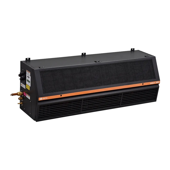
Overview 1.1.2. Outdoor Unit The outdoor unit is specifically designed for Vertiv™ Liebert® SRC-G Indoor unit, which comprises compressor as an integral part of outdoor assembly. Description Description Condenser fan Service valve Outdoor unit cabinet Electrical box cover plate Figure 1-2 Liebert® SRC-G Outdoor Unit Liebert SRC series is a comprehensive solution of indoor and outdoor units, Liebert SRC-G outdoor unit is a integral part of Liebert SRC-G unit. -
Page 13: Model Description
Overview 1.2. Model Description Vertiv™ Liebert® SRC-G series is fully-defined by 18 digits, as represented in Table 1-1. Table 1-1 Liebert® SRC-G Model Nomenclature Digit 1, 2, 3 Product Model Digit 12 Compressor Small Room Cooling Scroll Digit 4,5 Net Cooling Capacity kW Rotary 03, 07 &... -
Page 14: Basic Performance Parameters
Overview 1.3. Basic Performance Parameters The basic performance parameters of the Vertiv™ Liebert® SRC-G are shown in Table 1-2. Table 1-2 Basic Performance Parameters of Liebert® SRC Units Model Nominal Cooling Capacity* Power* SRC03GES 0.93 TR 1.03 kW SRC07GES 2.13 TR 2.27 kW... - Page 15 Figure 1-4 EC Fan • Thermal Expansion Valve (TXV) Vertiv™ Liebert® SRC-G unit has an external equalizer type Thermal Expansion Valve (TXV) that collects temperature and pressure signals simultaneously to accurately regulate the refrigerant flow into the evaporator. Figure 1-5 Thermal Expansion Valve (TXV) •...
-
Page 16: Outdoor Unit
• Return Air Temperature Sensor (PEX1142) Vertiv™ Liebert® SRC-G unit is provided with return air temperature sensor which not only reads the inlet air temperature returning from the room, but also provides value of the relative humidity of the returning air. It is used to modulate the cooling effect of the unit by controlling the return air temperature, and also maintains the humidity by eliminating the excess moisture in the room. -
Page 17: Control Panel
The power SPD is used for surge over-voltage protection in second level (C-level) single-phase (or three- phase) AC power supply. It provides status indication and alarm function of the unit, thereby facilitates easy maintenance. Vertiv™ | Liebert® SRC-G | User Manual... -
Page 18: Additional Components (Optional)
Overview 1.5. Additional Components (Optional) 1.5.1. Remote Monitoring Vertiv™ Liebert® SRC-G series adopts the SNMP communication protocol; through the configured LAN port. The Liebert SRC-G can communicate with the host computer and receives the control instructions of the host software. -
Page 19: Environmental Conditions Requirements
-25 °C to +55 °C (transport environment temperature: -40 °C to +70 °C) Total transportation and storage time should not exceed six months, otherwise the Storage time performance of the system needs to be re-calibrated. Vertiv™ | Liebert® SRC-G | User Manual... -
Page 20: Refrigerant Charging Requirement
Do not use sub-standard quality refrigerant as it may cause an extensive damage to the system. Vertiv does not undertake any responsibility for all the related consequences that are result from using a low quality or an inferior refrigerant. -
Page 21: Chapter 2: Mechanical Installation
Check that the fittings are complete and the components are intact against the packing list. If any parts are found missing or damage, report immediately to the local office of the carrier and Vertiv representative. Do not accept a damaged unit. -
Page 22: Installation Notes
Mechanical Installation 2.2. Installation Notes • Vertiv™ Liebert® SRC-G indoor unit is wall mounted and the outdoor unit is installed outside of equipment/ computer room or on the floor of other rooms, still it is recommended to provide adequate maintenance space... -
Page 23: System Installation Arrangement
Liquid line Service valve Gas line flared connection Liquid line Trap (as per piping details) Liquid line flared connection Gas line Filter & drier Gas line service valve Expansion valve Figure 2-2 System Arrangement Diagram Vertiv™ | Liebert® SRC-G | User Manual... -
Page 24: System Installation Mode
Outdoor Unit Indoor Unit Mounting floor Seal for pipe protection through wall Condensate drain pipe Liquid line Wall Gas line (1:100) Figure 2-3 Indoor Unit is Placed Higher than Outdoor Unit during Installation Vertiv™ | Liebert® SRC-G | User Manual... - Page 25 The maximum height difference allowed in this case is 5 m. When the indoor unit is installed at a lower level than the outdoor unit, maximum allowed height difference is 30 m (refer Figure 2-4). Maximum allowed equivalent piping length is 60 m. Vertiv™ | Liebert® SRC-G | User Manual...
-
Page 26: Mechanical Installation
Table 2-2 represents dimension and operational weight of the all indoor units. Description Description Liebert SRC Indoor Unit Maintenance Space Figure 2-5 Maintenance Space of Liebert SRC-G Model Vertiv™ | Liebert® SRC-G | User Manual... - Page 27 Dimensions (W × D × H) Operational Model Weight (kg) SRC03GES 640 x 355 x 490 SRC07GES 1100 x 355 x 490 SRC07GET 1100 x 355 x 490 SRC11GET 1400 x 355 x 490 Vertiv™ | Liebert® SRC-G | User Manual...
-
Page 28: Dimension And Weight Of The Outdoor Unit
Dimensions (W × D × H) Operational Model Weight (kg) SRC03GES 970 x 410 x 610 SRC07GES 970 x 410 x 800 SRC07GET 970 x 410 x 800 SRC11GET 970 x 410 x 1170 Vertiv™ | Liebert® SRC-G | User Manual... -
Page 29: Indoor Unit Installation Procedure
• Vertiv recommends that the site preparation is defined as per the requirements. However, if these requirements are not met, Vertiv recommends that rectifications to be made on the site in order to comply with the specified requirements and conditions. -
Page 30: Indoor Unit Installation
• Do not install other devices (such as smoke detector) over the indoor cabinet. Vertiv™ Liebert® SRC-G can generate condensate water. Water leakage can cause damage to other equipment nearby. Do not install the units in the vicinity of any precision equipment. The installation site must have the facility of drainage piping. - Page 31 Follow the step by step procedure to install the Liebert® SRC-G Indoor unit. Step 1: Figure 2-10 illustrates the drill holes of dimension Ø 10 mm for expansion bolts and their locations for SRC03GES SRC07GES, SRC07GET, and SRC11GET models Vertiv™ | Liebert® SRC-G | User Manual...
- Page 32 Figure 2-10 Location of the Expansion Bolt Holes Table 2-5 Dimension of the Expansion Bolt Holes Model SRC03GES 288.6 SRC07GES 288.6 1014 SRC07GET 288.6 1014 SRC11GET 288.6 1315 Figure 2-11 Location of the Expansion Bolt Holes Vertiv™ | Liebert® SRC-G | User Manual...
- Page 33 ‘forklift’. It is recommended installation should be carried out only by trained professionals. All the illustration are for reference only, the actual site mounting may differ as per requirement, consult Vertiv professional before installation. Vertiv™ | Liebert® SRC-G | User Manual...
-
Page 34: Installation Of Outdoor Unit
Long waist hole (4-10x12) Figure 2-13 Hole Dimension of Outdoor Unit Base (Vertical Installation) For vertical installation, first fix the bracket frame to the installation floor, then install the outdoor unit on the base frame. Vertiv™ | Liebert® SRC-G | User Manual... - Page 35 • Use 5# angle iron for bracket, when two units are installed with one above the other. • Use 6.5# channel steel for bracket, when three units are installed with one above the other. Vertiv™ | Liebert® SRC-G | User Manual...
-
Page 36: Refrigeration Piping Connection General Principles
5. The equivalent lengths of the components are shown in Table 2-9, and the resistance losses caused by the elbows and valves have been taken into account. Consult Vertiv representative to confirm the suitability as per the site conditions. Table 2-7 Standard Piping Dimensions... -
Page 37: Quick Thread Connector Installation Notes
• Refrigerant piping between the indoor and the outdoor units (gas and liquid piping). • Drain piping connections of the indoor unit. Prior to start-up, ensure that all piping connections have been completed and there is no leakage in the system. Vertiv™ | Liebert® SRC-G | User Manual... -
Page 38: Connecting Refrigerant Piping
• If the piping equivalent length exceeds 30 m then ‘Long piping kit’ should be added. • If the equivalent pipe length exceeds 60 m, please consult Vertiv local representative for details. • Copper pipe with outer diameter of 16/13 mm, wall thickness requirement is 0.8 mm; copper pipe with outer diameter of 10 mm, wall thickness requirement is 0.6 mm. - Page 39 Figure 2-16. Ensure service valve of outdoor unit are firmly close during piping connection, as the outdoor unit is pre-charged with refrigerant equivalent to 10 m piping, refer Figure 2-11 for pre-charged details. Vertiv™ | Liebert® SRC-G | User Manual...
-
Page 40: Connecting Drain Piping Of Indoor Unit
Ensure that the screws are firmly fixed and can sustain weight of the control panel. 3. Ensure the cables connecting to the control panel to indoor unit and outdoor unit are properly routed and Vertiv™ | Liebert® SRC-G | User Manual... -
Page 41: Charging Refrigerant
Mechanical Installation carefully insulated. Contact Vertiv technical personnel before selecting the location for control pane. 4. Its recommended terminate incoming power in control panel via external isolation in proximity of control panel (refer Figure 2-7). This isolation in case of isolation switch shall comply to IEC60204-1 (black -white color scheme). -
Page 42: Adding Refrigerant For Long Piping System
• If the pipe length exceed 10 m, then refrigerant cylinder is kept up-side-down (depending on the size of the cylinder, consult Vertiv local representative for details) during the charging of the refrigerant to ensure that the refrigerant is charged into the refrigeration system in a liquid state. -
Page 43: Mechanical Installation Checklist
Mechanical Installation • A certain type of POE lubricant that is directly supplied by Vertiv must be used, otherwise the compressor may get damaged. When charging the refrigeration system with oil, consult Vertiv representative for more details on adding the lubricant oil. -
Page 44: Chapter 3: Electrical Installation
Electrical Installation Chapter 3: Electrical Installation In this chapter, the electrical installation of Vertiv™ Liebert® SRC-G unit is explained in-depth to help users with the various activities, which include work introduction and installation notes, connecting power cables of the indoor and outdoor units, connecting the control cables, and the installation inspection. -
Page 45: Installation Notes
6. The front end of the unit needs to be equipped with a power-disconnection device to ensure safe operation. 7. Use screws, guide rails, or other modes to fix the device firmly during the installation process to avoid movement or shaking during the start-up or operation mode. Vertiv™ | Liebert® SRC-G | User Manual... -
Page 46: Indoor Unit Connection
3. Route the power cable through the cover plate wire hole and connect it to the barrier terminal lock, refer Figure 3-2 for terminal connection. Figure 3-2 Control Field Connection Terminals for Single Phase Vertiv™ | Liebert® SRC-G | User Manual... - Page 47 • Install a MCB switch before the power supply input of the indoor unit to easily isolate the unit for the maintenance. Connect the power cable to the MCB switch and then to the unit. • A RCCB should be installed before the indoor unit power supply input. Vertiv™ | Liebert® SRC-G | User Manual...
-
Page 48: Outdoor Unit Connection
Figure 3-4 Figure 3-5 show the amplified connection terminals for SRC07GES and SRC07GET respectively. Description Outdoor terminal block Figure 3-3 Outdoor Cable Terminal Location Figure 3-4 Cable Connector Terminals (SRC07GES, SRC03GES) Vertiv™ | Liebert® SRC-G | User Manual... -
Page 49: Control Panel Connection
Following table shows applicability of pins. During installation refer sticker pasted on machine for actual connection. Pins other then presented in below table are applicable for all machines. Vertiv™ | Liebert® SRC-G | User Manual... - Page 50 • The AC system will generate an audible alarm and LCD screen on microprocessor controller will display the corresponding alarm information. If a computer using Vertiv host monitoring software is connected, the alarm will be displayed on it too.
- Page 51 Figure 3-7 Monitoring the Networking of Two Liebert® SRC Units • Teamwork/Sequencing connection Vertiv™ Liebert® SRC-G units support the teamwork control function of up to 8 units. If user needs to use the teamwork control function, then connect the teamwork control terminals SEQ CH+, SEQ CL+, SEQ CH- and SEQ CL- between the units in series.
-
Page 52: Electrical Installation Checklist
All the cables and connector connections, including the fixing blocks, are firmly and appropriately fixed. After confirming the preceding points, user can replace the electrical plate and start start-up inspection & functional testing. Vertiv™ | Liebert® SRC-G | User Manual... -
Page 53: Chapter 4: Start-Up Commissioning
Start-up Commissioning Chapter 4: Start-up Commissioning This chapter introduces the start-up inspection and function testing of Vertiv™ Liebert® SRC-G units. 4.1. Start-up Inspection Before commissioning the unit, inspect the status of components of the unit. Refer Table 4-1 for the list of inspection requirements. -
Page 54: Function Testing
5°C (10°F) higher than the indoor temperature. If the compressor stops working, it means that the cooling function is normal. Restore the temperature setpoint to the default or the original value after the test. Vertiv™ | Liebert® SRC-G | User Manual... -
Page 55: Dehumidifying
Note that during the testing process, if the indoor temperature is 3 ºC higher than the temperature setpoint, the system may enter in ‘Forced Cooling Mode’ and the dehumidification demand will not be responded. Restore the humidity setpoint to the default or the original value after the test. Vertiv™ | Liebert® SRC-G | User Manual... -
Page 56: Chapter 5: Controller Operation Instructions
Controller Operation Instructions Chapter 5: Controller Operation Instructions This chapter provides a detailed description on feature, appearance, color screen, control buttons, control interface and menu structure of Vertiv™ Liebert® SRC-G units. 5.1. Feature The microprocessor controller has the following features •... -
Page 57: Control Interface
The microprocessor controller has five control buttons, as shown in Figure 5-2. The functions of these control buttons are described in Table 5-1. Description Description On/Off button Up button Enter button Down button ESC button Figure 5-2 Control Buttons Vertiv™ | Liebert® SRC-G | User Manual... - Page 58 8. Press the Up or Down button to select the parameter option. 9. After selecting, press the Enter button to confirm. The parameter will take effect. 10. Press the Esc button to return to the previous menu screen. Vertiv™ | Liebert® SRC-G | User Manual...
-
Page 59: Power On Screen
After the unit is powered On, the Main Menu screen will be displayed after 10 seconds. Refer Figure 5-4 for better understanding. Description Description Return air temperature Sequencing (teamwork) status Return air humidity Machine working status Current alarm status Unit ID Current date Time Figure 5-4 Summary Screen Vertiv™ | Liebert® SRC-G | User Manual... -
Page 60: Password Screen
Password screen. If you press the Enter button on the Password screen instead of entering a password, the menu settings can only be viewed, but no parameters can be changed. Vertiv™ | Liebert® SRC-G | User Manual... -
Page 61: Main Menu Screen
Figure 5-6 Main Menu Options 1 Figure 5-7 Main Menu Options 2 In case of sequencing or unit is connected in a network with other units then lowest ID unit is a Host and others are spares. Vertiv™ | Liebert® SRC-G | User Manual... -
Page 62: Menu Structure
In the Main Menu select ‘Alarm Menu’ to access the alarm menu option as shown in Figure 5-8. In the Alarm Menu option, user can access Alarm Status option, Alarm History option and Alarm Setting as shown in Figure 5-9. Figure 5-8 Alarm Menu in Menu Window Vertiv™ | Liebert® SRC-G | User Manual... -
Page 63: Alarm Status
Figure 5-10. Figure 5-10 Alarm Status Screen 5.4.3. Alarm History In the Alarm Menu select ‘Alarm History’ to access the alarm history details as shown in Figure 5-11. Figure 5-11 Alarm History Screen Vertiv™ | Liebert® SRC-G | User Manual... -
Page 64: Alarm Setting
For example, “General alarm”. In case of common alarm case, the pin status during alarm is defined in this parameter. This status could be NO/NC. • Miscellaneous For example, “Clear alarm history” which clears alarm history. Vertiv™ | Liebert® SRC-G | User Manual... -
Page 65: Setpoint Menu
On/off Record as shown in Figure 5-14. Figure 5-14 System Status Options 5.6.1. Analog Status Options In the System Menu option, select ‘Analog Setting’ option to access the following setting option shown in Figure 5-15. Vertiv™ | Liebert® SRC-G | User Manual... -
Page 66: Input/Output Status Options
In the System Menu option, select ‘I/O Status’ option to access the following status options as shown in Figure 5-16. Figure 5-16 I/O Status Options 5.6.3. Time/Date Options In the System Menu option, select ‘Time/date’ option to access the following setting option shown in Figure 5-17. Figure 5-17 Time/Date Screen Vertiv™ | Liebert® SRC-G | User Manual... -
Page 67: Run Time Options
Figure 5-19. Figure 5-19 On/Off Record Screen Further click on the individual option to access evaporator fan and Compressor Settings and shown in Figure 5-20. Vertiv™ | Liebert® SRC-G | User Manual... -
Page 68: System Menu
• Supply power monitoring parameters such as over-voltage, under voltage frequency offset and Pwr frequency. • To safeguard compressor and fan during normal operation, Operation delay parameters such as EvapFanStart, EvapFanStop, Cp minOn, Cp minOff, cold Start defines various. Vertiv™ | Liebert® SRC-G | User Manual... -
Page 69: Outdoor Unit Options
Figure 5-22 Protocol Setup Screen 5.7.2. Outdoor Unit Options In the System Menu option, select ‘Outdoor Unit’ option to access the outdoor unit option shown in Figure 5-23. Figure 5-23 Pressure Setting Screen Vertiv™ | Liebert® SRC-G | User Manual... -
Page 70: Optional Function Options
In the System Menu option, select ‘set password’ option to access the following setting option shown in Figure 5-25. Refer Section 5.3.4 for example of password access. Figure 5-25 Password Setting Screen The default passwords are factory set for more details contact Vertiv local representative. Vertiv™ | Liebert® SRC-G | User Manual... -
Page 71: Help Menu
In the main menu select ‘Help Menu’ option to view detail of the unit as shown from Figure 5-26 to Figure 5-28 Figure 5-26 Version Info Screen Figure 5-27 Controller Info Screen Figure 5-28 Contact Info Screen Vertiv™ | Liebert® SRC-G | User Manual... -
Page 72: Display Settings
In the Main Menu select ‘Display Menu’ option to access display and Language settings option as shown in Figure 5-29. Figure 5-29 Display Settings Screen 5.10. Sequencing Status In the Main Menu select ‘Sequencing Status’ to access the sequencing details as shown from Figure 5-30. Figure 5-30 Sequencing Status Screen Vertiv™ | Liebert® SRC-G | User Manual... -
Page 73: Sequencing Setting
In case of fault with master unit, next lowest ID unit is promoted as a master. Once the unit is out of fault it can again resume as a master. Total Mach This option represents total units in the network. Vertiv™ | Liebert® SRC-G | User Manual... - Page 74 Cas Mode is selected by “ON”. Cascading mode is activated when Cas Temp is reached. This mode is auto turned Off when once Cas Diff is achieve. STBY BLWR The status of evaporator fans of standby units can be selected using “STBY BLWR”. Vertiv™ | Liebert® SRC-G | User Manual...
-
Page 75: Chapter 6: System Operation And Maintenance
System Operation and Maintenance Chapter 6: System Operation and Maintenance This chapter explains the system maintenance of Vertiv™ Liebert® SRC-G units, including electrical inspection, indoor unit maintenance, outdoor unit maintenance and maintenance inspection checklist. • Switch Off the circuit breaker and cut-off the unit power supply before maintenance unless the power is necessary for commissioning the unit. -
Page 76: Indoor Unit Maintenance
This unusual airflow obstruction can also affect to the other system components due to reduction in air volume. Refer Figure 6-2 for better understanding. Vertiv™ | Liebert® SRC-G | User Manual... -
Page 77: Drain Pipe
Description Fan Box EC Fan Front Panel Figure 6-2 Vertiv™ Liebert® SRC-G EC Fan Location 6.2.3. Drain Pipe Figure 6-3 shows drain pipe connection; inspect water pan periodically for normal operation of the drain pipe. Ensure that no foreign matter or leakage exists in the drain pipe. -
Page 78: Power Spd
The Thermal Expansion Valve keeps the evaporator supplied with enough refrigerant to satisfy load conditions. Its proper operation can be determined by measuring the superheat level. The correct superheat setting is 5.6 °C to 8.3 °C (10 °F to 15 °F). Vertiv™ | Liebert® SRC-G | User Manual... -
Page 79: Outdoor Unit Maintenance
Table 6-1 Typical Liquid (Discharge) Pressure and Gas (Suction) Pressure Items psig Low pressure 100 to 159 0.7 to 1.12 Low-pressure setting 0.37 Low-pressure recovery point 0.56 High pressure 284 to 526 2.0 to 3.7 High-pressure setting High-pressure recovery point Vertiv™ | Liebert® SRC-G | User Manual... -
Page 80: Compressor
Avoid touching or contacting the residual gas and oils in compressor with exposed skin. Wear long rubber gloves to handle contaminated components. Check the following particulars before replacing the compressor Vertiv™ | Liebert® SRC-G | User Manual... - Page 81 Release of refrigerant to the atmosphere is harmful to the environment. Refrigerant must be recycled in accordance with state and local regulations. Vertiv™ | Liebert® SRC-G | User Manual...
-
Page 82: Monthly Routine Maintenance
Check if refrigerant piping is reliably supported Check system circulation and moisture content (observed through sight Refrigerant system glass) Check Thermal Expansion Valve (TXV) is firmly connected Vertiv™ | Liebert® SRC-G | User Manual... -
Page 83: Routine Maintenance And Inspection (Semi-Annually)
Check if the refrigerant piping are properly supported Check all electrical connections are firmly tightened Electrical board Check the surface of the circuit board for signs of corrosion Vertiv™ | Liebert® SRC-G | User Manual... -
Page 84: Chapter 7: Troubleshooting
Disconnect the system power supply, and then restart Display abnormal Loose connection between keypad Check the connections are firmly fixed after powering Off, and control board the unit and then restart the unit Vertiv™ | Liebert® SRC-G | User Manual... - Page 85 The screen display is normal, the Contact Vertiv representative for maintenance support or button does not The display board setting is faulty engineering assistance respond, the device is running normally...
- Page 86 Adjust remote control parameters Remove the obstruction at the return air outlet of the unit, Airflow loss alarm Return air volume is small clean the return air filter, or contact Vertiv representative for maintenance support or engineering assistance Return air temperature sensor...
- Page 87 User Needs to Check Particulars or Processing Method Check if the condensing pressure sensor cabling is Pressure sensor Pressure sensor failure firmly connected or contact Vertiv representative for failure maintenance support or engineering assistance The unit is in operation and the...
-
Page 88: Appendix I: Menu Structure
HI PRESS MACHINE CASCADING RET CAL LOW PRESS MACHINE CASACDING SUPP CAL CUSTOM 1 TEMPERATRE CASCADING PRESS1 CUSTOM 2 DIFFERENTIAL PHASE A ROTATE MN PHASE B RESET RUN MN PHASE C STBY BLOWER PWR FREQ Vertiv™ |Liebert® SRC-G | User Manual... - Page 89 © 2022 Vertiv Group Corp. All rights reserved. Vertiv™ and the Vertiv logo are trademarks or registered trademarks of Vertiv Group Corp. All other names and logos referred to are trade names, trademarks or registered trademarks of their respective owners. While every precaution has been taken to ensure accuracy and completeness here, Vertiv Group Corp.
Need help?
Do you have a question about the Liebert SRC-G Series and is the answer not in the manual?
Questions and answers
Joshua123456