
Related Manuals for Vertiv Liebert XDC


Summary of Contents for Vertiv Liebert XDC
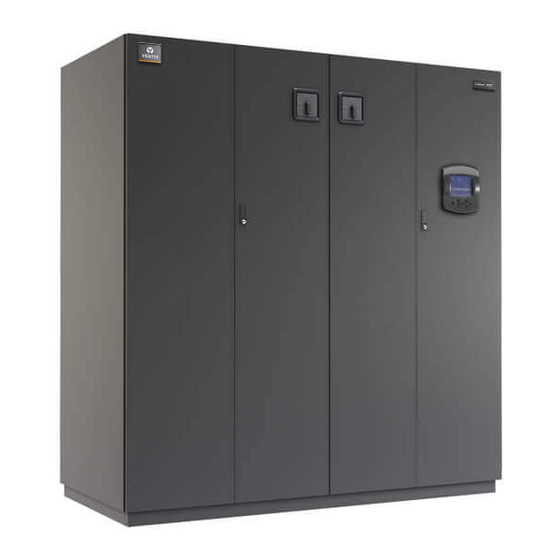
- Page 1 Liebert® XDC™ 50 & 60 Hz, 130 & 160kW Nominal Cooling Capacity; Model Revision 5 or Higher User Manual...
- Page 2 Technical Support Site If you encounter any installation or operational issues with your product, check the pertinent section of this manual to see if the issue can be resolved by following outlined procedures. Visit https://www.VertivCo.com/en-us/support/ for additional assistance.
-
Page 3: Table Of Contents
2.1.1 Product/System Description 2.2 Equipment Inspection 2.3 Equipment Handling 2.3.1 Handling the Liebert XDC While it is on Skid and Packaged 2.3.2 Unpacking the Liebert XDC 2.3.3 Removing the Unit from the Skid Using a Forklift 2.3.4 Removing the Unit from the Skid using Rigging 2.3.5 Moving the Liebert XDC Using Piano Jacks... - Page 4 6.8 Liebert iCOM User Menu Screens 6.9 Liebert iCOM Service Menu Icons and Legend 6.10 Liebert iCOM Service Menu Screens 7 Start the Liebert XDC with Liebert iCOM 7.1 Checklist for Liebert XDC Startup 8 Alarm Descriptions and Solutions 8.1 Alarm Descriptions 8.2 Warning Descriptions...
-
Page 5: Important Safety Instructions
Save These Instructions This manual contains important safety instructions that should be followed during the installation and maintenance of the Liebert XDC. Read this manual thoroughly before attempting to install or operate this unit. Only qualified personnel should move, install or service this equipment. - Page 6 Water leakage can result in severe property damage and loss of critical data center equipment. Do not locate unit directly above any equipment that could sustain water damage. Vertiv recommends installing monitored leak detection equipment for the unit and supply and return lines.
- Page 7 Do not locate unit directly above any equipment that could sustain water damage. Vertiv recommends installing monitored leak detection equipment for the unit and the supply and return lines. NOTE: This document must be used with site specific documentation and documentation for other parts of the system (heat rejection devices and cooling modules).
- Page 8 This page intentionally left blank. Vertiv | Liebert® XDC™ User Manual |...
-
Page 9: Product Description
Heat rejection is available in two options: an outdoor air-cooled condenser and a water/glycol condenser. See Figure 2.1 below below. The Liebert XDC monitors room conditions and prevents coil condensation by maintaining the refrigerant being pumped to the cooling modules at a temperature above the room dew point. All functions, such as temperature control, switching pumps (if necessary), etc., are automatic. -
Page 10: Equipment Inspection
WARNING! Risk of unit falling over. Can cause injury or death. The Liebert XDC is top-heavy. Use extreme caution when moving and installing this unit. Use lifting equipment that is rated for the weight of the unit by an OSHA-certified rating organization. -
Page 11: Unpacking The Liebert Xdc
NOTICE Risk of improper storage. Can cause unit damage. Keep the Liebert XDC upright, indoors and protected from dampness, freezing temperatures and contact damage. NOTICE Risk of overtightening securing straps. Can cause damage to panels. Place a protective material between the straps of the piano jacks and the unit. Ensure that the straps are not tightened to a point of damaging panels. -
Page 12: Removing The Unit From The Skid Using Rigging
4. Lift the unit to a height that it is not being support by the skid. 5. Move the skid from under the unit. Figure 2.3 Use a forklift to remove the Liebert XDC from the skid 2.3.4 Removing the Unit from the Skid using Rigging Use the center of gravity indicators on the unit to position the slings. -
Page 13: Moving The Liebert Xdc Using Piano Jacks
3. Put protective material between the Liebert XDC and the piano jacks and straps. 4. Secure the Liebert XDC to the piano jacks. 5. Release the the Liebert XDC from the straps securing it to the lifting mechanism and move the mechanism away from the unit. -
Page 14: Removing The Unit From The Piano Jacks
Lower the Liebert XDC as far as the piano jacks will allow. 2. Undo all strapping holding the piano jacks to the unit. 3. Lift one end of the Liebert XDC off one piano jack with a pry bar or similar device, taking care not to damage the unit’s cabinet. -
Page 15: Installation
Install the Liebert XDC according to the site specific documentation and secure the unit to the floor. The Liebert XDC can be installed near a wall or another Liebert XDC. However, there must be at least 3 feet (92cm) clearance in front of the Liebert XDC as service access for components in the unit. - Page 16 Figure 3.2 Piping locations Table 3.2 Liebert XDC piping connection sizes Piping Outlet Connection Sizes, OD Cu, inches 50/60Hz XDC160 2-1/8 1-1/8 1-3/8 Source: DPN001599 Vertiv | Liebert® XDC™ User Manual |...
-
Page 17: Placing The Liebert Xdc On A Floor Stand
8. Maintaining the alignment of the Liebert XDC and the floor stand, lower the Liebert XDC onto the floor stand. 9. Connect the hot gas refrigerant lines from the Liebert XDC to the floor stand with 1-3/8" tubing (see Figure 3.3 on the next page andFigure 3.4 on page 20). - Page 18 Figure 3.3 Water/glycol Liebert XDC on a floor stand—positioning and piping connections Vertiv | Liebert® XDC™ User Manual |...
- Page 19 Table 3.3 Liebert XDC water/glycol piping connection sizes Model Piping Outlet Connection Sizes, OD Cu, inches 50/60Hz XDC160 2-1/8 1-1/8 1-3/8 2-1/2 2-1/8 or 2-5/8 1. Threaded female connection 2. 2-1/8" for 1" water regulating valve; 2-5/8" for 1-1/4" water regulating valve Source: DPN001419 Rev.
-
Page 20: Positioning The Liebert Xdc With Floor Stand
Install the Liebert XDC according to the site-specific documentation and secure the unit to the floor. The Liebert XDC can be installed near a wall or another Liebert XDC. There must be at least 3 feet (914mm) clearance in front of the Liebert XDC for service access. When the Liebert XDC is combined with the optional water/glycol floor stand, Vertiv recommends leaving 3 feet (914mm) of clearance on the left side of the unit. - Page 21 A Liebert XDC on a floor stand is 102 inches (2591 mm) high (see Figure 3.5 below). The unit can be raised or lowered 1.5 inches (38.1 mm) with the leveling feet. Figure 3.5 Dimensions and clearances for Liebert XDC on floor stand...
-
Page 22: Electrical Considerations
Liebert XDC’s rating plate. Connect cables for high voltage supply to the electrical box in the Liebert XDC according to Figure 3.1 on page 15, Figure 3.7 on page 24 and Figure 3.8 on page 25 and make sure that the phases are correctly connected. -
Page 23: Connecting High-Voltage Cables
3.2.2 Connecting High-Voltage Cables Turn the Liebert XDC’s primary disconnect switch to the Off position (see Figure 3.6 below). Open the front doors and push down on the enclosure cover latch to open the hazardous voltage enclosure cover. Figure 3.6 Front view of Liebert XDC and electrical enclosures... - Page 24 2. Determine which knockouts in the electrical enclosure will be used and remove them (see Figure 3.7 below). Figure 3.7 Electrical enclosure knockout locations for field wiring Vertiv | Liebert® XDC™ User Manual |...
- Page 25 60Hz models and Figure 3.9 below andFigure 3.11 on the next page for 50Hz models). Figure 3.8 60Hz models, high voltage connections—primary disconnect switch Figure 3.9 50Hz models high voltage connections—primary disconnect switch Vertiv | Liebert® XDC™ User Manual |...
- Page 26 Figure 3.10 60Hz models high voltage connections—secondary disconnect switch Figure 3.11 50Hz models high voltage connections—secondary disconnect switch Vertiv | Liebert® XDC™ User Manual |...
-
Page 27: External Pump Overloads
3.3 External Pump Overloads The Liebert XDC is shipped with external pump overload with trip point settings and DIP switch settings for normal operations. The trip points are in increments of 0.25A and should not be changed from the factory settings. For 460V 60Hz and 380-400V 50Hz units, the trip point is set at 1.5A (Figure 3.12 below). -
Page 28: Extra Low Voltage Connections
Figure 3.17 on page 31. 3. User interface and temperature/humidity sensor wire is NEC Class 2. All electrical installation must comply with all national, state and local requirements. Figure 3.15 Liebert XDC heat rejection connection points Vertiv | Liebert® XDC™ User Manual |... - Page 29 Figure 3.16 Connecting remote temperature/humidity sensors Vertiv | Liebert® XDC™ User Manual |...
- Page 30 Each cable must make three passes through the ferrite bead. Locate the ferrite bead on top of the electric box. See instruction sheet provided with the cable assembly. 9. Factory-installed ferrite bead (when provided). Cable passes through ferrite bead three times. Vertiv | Liebert® XDC™ User Manual |...
- Page 31 3.16 on page 29). 3. Connect the Unit End of the sensor cable to P4 on the CAN Isolator inside the Liebert XDC (see Figure 3.16 on page 29). Secure the terminal plug on the cable shield to the into the terminal plug adjacent to P2 (see Figure 3.16 on page 29).
- Page 32 Output, IGM and Remote Shutdown, if applicable. See terminal strip descriptions in Figure 3.18 on the facing page. Field Connections—Air-Cooled Units only Connect field wiring to heat rejection connection terminals on the handy box as shown in Figure 3.15 on page 28. Vertiv | Liebert® XDC™ User Manual |...
- Page 33 Figure 3.18 Extra Low Voltage field connection points Vertiv | Liebert® XDC™ User Manual |...
-
Page 34: Remote Sensor Installation-Proper Placement
Liebert XDC. Vertiv recommends installing the sensors in different areas near the cooling modules served by the Liebert XDC. If the return air side of the primary air mover, such as a Liebert DS, represents the conditions where the Liebert XD cooling modules are located, one sensor could be placed there. - Page 35 Figure 3.20 Suggested remote sensor placement Do not install the sensors where ambient air might cause false readings, for example, near unsealed doors or windows, or areas with stagnant air. Vertiv | Liebert® XDC™ User Manual |...
- Page 36 This page intentionally left blank. Vertiv | Liebert® XDC™ User Manual |...
-
Page 37: Piping And Filling With Refrigerant: R-134A And R-407C Circuits
NOTE: Follow all local codes on maximum length and size of refrigerant lines. Connect the main pipes between the Liebert XDC and the Liebert XD cooling modules according to site specific documentation and the configuration guide for the Liebert XD system. -
Page 38: Liebert Xdc Interconnection With Liebert Xd Cooling Module
All piping must be ASTM (American Society for Testing and Materials) Type ACR copper pipe. The Liebert XDC may be connected to Liebert XD cooling modules with either Liebert’s XD prefabricated piping assembly or with rigid, off-the-shelf piping. In either setup, piping for the Liebert XD system is arranged in a manner similar to piping for a chilled water system. -
Page 39: Piping Installation-R-134A Pumped Circuit
4.4.1 Piping Installation—R-134a Pumped Circuit Vertiv recommends venting the relief pressure of the Liebert XDC (located at the top of the receiver) outside of the conditioned space where it is open to the atmosphere. 4.4.2 Bypass Flow Controllers Two bypass flow controllers are required to ensure the Liebert XDC pumps operate within the optimum range. - Page 40 Figure 4.3 Bypass flow controller arrangement Figure 4.4 Bypass flow controller piping Vertiv | Liebert® XDC™ User Manual |...
-
Page 41: Piping Details-Shutoff/Isolation Valves
4.5 Piping Details—Shutoff/Isolation Valves Isolation valves must be installed on the Liebert XDC’s refigerant circuit to permit maintenance on the unit (see Figure 4.5 below.) Figure 4.5 General piping details Evacuation and Leak Check—R-134a Pumped Circuit Open all service valves, including those located outside of the Liebert XDC. - Page 42 4.5 on the facing page and Table 4.6 on the facing page are based on a fully loaded system. Additional charge may be required for lightly loaded systems. Table 4.3 System R-134a charge for a Liebert XDC with any model Liebert XDH/Liebert XDO/Liebert XDV/Liebert XDCF Per Liebert XD Unit...
- Page 43 6ft Liebert XD Flex Pipe Liebert XDH/Liebert XDO/Liebert XDV/Liebert XDCF/Liebert XDR supply 0.27 lb. (0.126) 8ft Liebert XD Flex Pipe Liebert XDH/Liebert XDO/Liebert XDV/Liebert XDCF/Liebert XDR supply 0.33 lb. (0.15) 10ft Liebert XD Flex Pipe Liebert XDH/Liebert XDO/Liebert XDV/Liebert XDCF/Liebert XDR supply Vertiv | Liebert® XDC™ User Manual |...
-
Page 44: Calculating Refrigerant Charge-Example
R-134a refrigerant required for one system combining a Liebert XDC with Liebert XD cooling modules (Liebert XD CoolFrame, Liebert XDH, Liebert XDO and Liebert XDV). The example below combines one Liebert XDC with 20 Liebert XDV8 cooling modules. -
Page 45: Piping For Direct Expansion (Dx) Circuit-R-407C Air-Cooled Units
Installer must install a 400 psig pressure relief valve in each of the two R-407C refrigerant circuits of the Liebert XDC system. Do not install shutoff valves between the compressors and the pressure relief valves. - Page 46 185010G2 -30 to 100 (-34 to 38) DCSL415 179711G1 179713G1 -30 to 105 (-34 to 41) DCSL616 179711G2 181610G2 35 to 105 (2 to 41) DCSL616 179711G1 1. 120V heater 2. 230V heater Vertiv | Liebert® XDC™ User Manual |...
- Page 47 Figure 4.7 Installation data—Liebert Lee-Temp, one-circuit, four-fan model Vertiv | Liebert® XDC™ User Manual |...
- Page 48 Figure 4.8 Installation data—Liebert Lee-Temp, one-circuit, high ambient six-fan model Vertiv | Liebert® XDC™ User Manual |...
- Page 49 Figure 4.9 Liebert XDC piping schematic and Liebert Lee-Temp heater pad wiring Vertiv | Liebert® XDC™ User Manual |...
- Page 50 Figure 4.10 General arrangement air-cooled Liebert XDC Liebert Lee-Temp Control Vertiv | Liebert® XDC™ User Manual |...
- Page 51 1-1/8 200 (60) 1-3/8 1-1/8 * Double risers are required when hot gas vertical rise is 15ft. (4.6m) or more (see Install Double Discharge Risers on page 45). Source: DPN000937, Pg. 3, Rev. 11 Vertiv | Liebert® XDC™ User Manual |...
- Page 52 Figure 4.11 DCSL616 piping connections—two refrigerant circuits connected for parallel flow Vertiv | Liebert® XDC™ User Manual |...
- Page 53 * Double risers are required when hot gas vertical rise is 15 feet or more (see Install Double Discharge Risers on page 45). Source: DPN000937, Pg. 4, Rev. 11 Figure 4.12 DCSL616 piping connections—two refrigerant circuits connected for parallel refrigerant flow Vertiv | Liebert® XDC™ User Manual |...
-
Page 54: Air-Cooled Condenser With Liebert Lee-Temp "Flooded Condenser" Head Pressure Control System-R-407C (Dx) Circuit
2. Attach refrigerant gauges to the suction and discharge service valves of the compressor. 3. Open all compressor service valves, including those located outside the Liebert XDC. 4. Connect the tank of dry nitrogen to the Schrader valves on the liquid lines and the hot gas lines. -
Page 55: Filling The Direct Expansion (Dx) Circuit-R-407C
3. Turn Off the main power to the unit. 4. Disconnect either the low-voltage wires from the #2 compressor contactors holding coils or remove the high-voltage fuses for the #2 compressor bank. Vertiv | Liebert® XDC™ User Manual |... - Page 56 Hot Gas Line, lb. (kg) 3.7 (1.7) 6.9 (3.1) 11.0 (5.0 2.2 (1.0) 15.7 (7.1) 3.1 (1.4) 23.0 (10.4) 4.5 (2.0) 1-1/8 39.3 (17.8) 7.8 (3.5) 1-3/8 59.8 (27.1 11.8 (5.4) 1-5/8 — 16.7 (7.6) Vertiv | Liebert® XDC™ User Manual |...
-
Page 57: System Refrigerant Charges Over 55Lb. (24.9Kg) Require Additional Oil
(the amount added along with the date it was added). This will be documented on a tag located at the tandem compressor and marked “Oil Added Field Service Record.” Refer to the Liebert XDC user manual, SL-16673, available at www.VertivCo.com. Figure 4.13 Additional oil requirements for refrigerant charge... - Page 58 Table 4.16 below. • Do not mix polyol ester (POE) and mineral-based oils. • Do not mix oils of different viscosities. Consult Vertiv or the compressor manufacturer if questions arise. Table 4.16 Compressor oil types Refrigerant Type Compressor Type...
-
Page 59: Installation Checklist
50Hz circuit breakers until the system is fully charged with refrigerant. Operating the pumps without a full refrigerant charge can result in equipment damage. 5. Connect Liebert XD cooling module piping to Liebert XDC. 6. Check all circuits of the system for leaks. - Page 60 This page intentionally left blank. Vertiv | Liebert® XDC™ User Manual |...
-
Page 61: Liebert Icom Control-Firmware Version Xp1.00.009.Std
The Liebert iCOM controller layout is shown in Figure 6.1 below; the keyboard functions are defined in Table 6.1 on the next page. The Liebert iCOM controller on the Liebert XDC displays the Unit View only. Figure 6.1 Liebert iCOM display components... - Page 62 Moves downward in a menu or reduces the value of a selected parameter. (Down Arrow) Left and Right Navigates through text and sections of the display. Arrow Keys Upper LED Blinking Red—Active, unacknowledged alarm exists Upper LED Solid Red—Active, acknowledged alarm exists Vertiv | Liebert® XDC™ User Manual |...
-
Page 63: Display Lamp Indicators
ALARM SILENCE / ? key is pressed. • The Amber lamp will be On if the Liebert XDC has been shut down at the I/O switch or if the unit has been shut down by an alarm condition. -
Page 64: Accessing Menus And Settings
The Liebert iCOM will display an overview of all connected cooling modules. It does not display a system view, which would include units other than the cooling modules. NOTE: The Liebert iCOM control screens display a setting to select a system view, but the Liebert XDC does not support a system view. -
Page 65: Entering The Password
Move to the next digit of the password with the Right arrow key. Select the numerals for all four digits with the same process. 8. After all four digits of the password have been entered, press the Enter key. Vertiv | Liebert® XDC™ User Manual |... -
Page 66: Changing Liebert Icom's Display Settings
7. Use the Up and Down arrow keys to make changes. 8. Press the Enter key to accept the changes. 9. Press the ESC key twice to return to Liebert iCOM’s user menu. Vertiv | Liebert® XDC™ User Manual |... -
Page 67: Changing Operational Settings
Figure 6.5 Display setup screen 6.5 Changing Operational Settings Changes to the Liebert XDC’s operation settings in the Set Alarms and Setpoints menus require a password. The User Menu password is 1490. The Service Menu password is 5010. From the home screen, press the Enter key to view the User Menu (see 6.7 on the next page). -
Page 68: Liebert Icom User Menu Icons And Legend
XDIO - Displays readings for the individual Service Contacts - Contains key contact smart modules; View Only information for service NOTE: Menu shows icons only; text is explanatory and does not appear on the Liebert iCOM display. Vertiv | Liebert® XDC™ User Manual |... -
Page 69: Liebert Icom User Menu Screens
Figure 6.6 Liebert XDC User Menu screen 6.8 Liebert iCOM User Menu Screens User menus report general cooling unit operations and status. User Menu screens employ a coding that begins in “U” and is followed by parameters and information, such as settings. Gaining access to some User Menu screens requires entering a password;... - Page 70 NOTE: This is not a true room temperature setpoint. The Liebert XDC has no heaters; it will try to cool as much as possible. If the Liebert XDC is able to cool the room to this setpoint, it will reduce its cooling action to try to keep the room temperature at or above this setpoint.
- Page 71 The supply refrigerant temperature is from the Liebert XDC to the modules. The range for the high supply refrigerant temperature alarm is from 33.8 to 95°F (1 to 35°C); the default is 80°F (26.7°C).
- Page 72 Sensor B Dew Point—Displays the dew point of the remote CAN Temp Humidity sensor designated at Sensor B. Supply Refrigerant Temperature—Displays the actual supply refrigerant temperature from the Liebert XDC to the modules. Vertiv | Liebert® XDC™ User Manual |...
- Page 73 Sensor B. Daily High Refrigerant Temperature—Shows the highest supply refrigerant temperature in a rolling 24 hour period from the Liebert XDC to the modules Daily Low Refrigerant Temperature—Shows the lowest supply refrigerant temperature in a rolling 24 hour period from the Liebert XDC to the modules.
- Page 74 Off, extending the life of the display and saving energy. Screen—Controls the screen layout. The Liebert XDC has one view, Unit View. Display Colors—Selects the background color. Inverted sets the display to show white font with blue background and Normal sets a white background with blue font.
- Page 75 Module Setup found in the Service menu (S910). Module Status—Indicates whether the smart module is connected to the CANbus. U901—Module Node ID/Label/Status. U902: Refrigerant Temperature—The temperature of the refrigerant entering the Liebert XD smart module. Vertiv | Liebert® XDC™ User Manual |...
- Page 76 U913—Displays the right fan status; possible values are ON, OFF and ON ECON. ON ECON indicates that only one fan is On. Figure 6.14 Liebert XDH smart module—each bank shown separately U905—Displays the temperature of the air leaving the Liebert XDH. Vertiv | Liebert® XDC™ User Manual |...
- Page 77 U910—Displays the temperature of the air leaving the Liebert XDO. U911—Displays the module type and calculated local module capacity; possible module types XDO16SK, XDO16SS and XDO20SS. U912—Displays the fan status; possible values are ON and OFF. Vertiv | Liebert® XDC™ User Manual |...
- Page 78 Each parameter shows a component, the hours that component has operated and the maximum time the component can operate before the next maintenance. U502—Pump 1 U503—Pump 2 U504—Compressor 1A U505—Compressor 1B U506—Compressor 2A U507—Compressor 2B Vertiv | Liebert® XDC™ User Manual |...
-
Page 79: Liebert Icom Service Menu Icons And Legend
Service Contacts - Contains key contact Set Alarms - Change settings for alarms information for service NOTE: Menu shows icons only; text is explanatory and does not appear on the Liebert iCOM display. Vertiv | Liebert® XDC™ User Manual |... -
Page 80: Liebert Icom Service Menu Screens
Figure 6.17 Liebert XDC Service Menu screen 6.10 Liebert iCOM Service Menu Screens Service menus allow customized settings for site operations. Service Menu screens employ a coding that begins in “S” and is followed by parameters and information, such as settings. Gaining access to most Service Menus requires entering a password;... - Page 81 The percent temperature adjustment required is calculated based on logic that is programmed into the control. These rules simulate the actions that would be taken by a human operator manually controlling the system. Vertiv | Liebert® XDC™ User Manual |...
- Page 82 This parameter is adjustable from 4.0 to 10.0°F (2.2 to 6.0°C). The factory default setting is 4.0°F (2.2°C). Minimum Control Point—Sets the minimum supply refrigerant temperature the Liebert XDC will maintain. This parameter is adjustable from 10 to 80°F (5.0 to 27.0°C). The factory default is 55°F (12.8°C).
- Page 83 Number of Alarms—Displays the number of alarms that have occurred with the unit’s Pump 1 Actual Bonus—Displays the actual calculation of wellness for the unit’s Pump 1. The unit will always take the value from the worst component for the next maintenance indication. Vertiv | Liebert® XDC™ User Manual |...
- Page 84 Number of Alarms—Displays the number of alarms that have occurred with the unit’s Pump 2 Actual Bonus—Displays the actual calculation of wellness for the unit’s Pump 2. The unit will always take the value from the worst component for the next maintenance indication. Vertiv | Liebert® XDC™ User Manual |...
- Page 85 Number of LP Alarms—Displays the number of low pressure alarms that have occurred with the unit’s Compressor 1A. Actual Bonus—Displays the actual calculation of wellness for the unit’s Compressor 1A. The unit will always take the value from the worst component for the next maintenance indication. Vertiv | Liebert® XDC™ User Manual |...
- Page 86 Number of LP Alarms—Displays the number of low pressure alarms that have occurred with the unit’s Compressor 1B. Actual Bonus—Displays the actual calculation of wellness for the unit’s Compressor 1B. The unit will always take the value from the worst component for the next maintenance indication. Vertiv | Liebert® XDC™ User Manual |...
- Page 87 Number of LP Alarms—Displays the number of low pressure alarms that have occurred with the unit’s Compressor 2A. Actual Bonus—Displays the actual calculation of wellness for the unit’s Compressor 2A. The unit will always take the value from the worst component for the next maintenance indication. Vertiv | Liebert® XDC™ User Manual |...
- Page 88 Number of LP Alarms—Displays the number of low pressure alarms that have occurred with the unit’s Compressor 2B. Actual Bonus—Displays the actual calculation of wellness for the unit’s Compressor 2B. The unit will always take the value from the worst component for the next maintenance indication. Vertiv | Liebert® XDC™ User Manual |...
- Page 89 1 indicates upon startup of a tandem bank of compressors pressure was not established for the compressors to be able to continue to run. 3 indicates that after operating normally the low-pressure switch opened and the tandem bank of compressors was unable to establish pressure. Vertiv | Liebert® XDC™ User Manual |...
- Page 90 Pump 1—Used to start the unit’s Pump 1. Pump 2—Used to start the unit’s Pump 2. 3P Actuator Input Request—A service tool to view the % call for cooling. Vertiv | Liebert® XDC™ User Manual |...
- Page 91 Hot Gas Valve 1 Analog—Sets the hot gas valve % open for Compressor Circuit 1. Hot Gas Valve 2 On/Off—Turns on the hot gas solenoid valve for Compressor Circuit 2. Hot Gas Valve 2 Analog—Sets the hot gas valve % open for Compressor Circuit 2. Vertiv | Liebert® XDC™ User Manual |...
- Page 92 Analog Output Ramp 1—Sets the value of Analog Output 1 value as a percentage. The factory default for the Liebert XDC is the hot gas valve 1. Analog Output Ramp 2—Sets the value of Analog Output 2 value as a percentage. The factory default for the Liebert XDC is the Call for Cooling.
- Page 93 Status Condensation Detect—Displays the status of the dry contact to communicate condensate detection at a module. Status Unit Ready—Shows unit status when a secondary device, such as a fire detection system, is employed. Vertiv | Liebert® XDC™ User Manual |...
- Page 94 Status LP1—Shows the status of the unit’s Compressor Circuit 1 low pressure switch input. Status LP2—Shows the status of the unit’s Compressor Circuit 2 low pressure switch input. Figure 6.32 Set alarms, page 1 of 7 Vertiv | Liebert® XDC™ User Manual |...
- Page 95 Customer Input 1 active when—Selects whether the input is normally closed or normally open. WARNING ACTIVATES ALARM RELAY—Sets the alarm relay (K3) to activate when a warning occurs. Reset Disabled Alarms—Resets disabled events. Vertiv | Liebert® XDC™ User Manual |...
- Page 96 Sensor B is below the user-specified alarm setpoint. Sets how the event is reported: as an alarm, a warning or a message. Specifies how long the control waits before reporting the event. Vertiv | Liebert® XDC™ User Manual |...
- Page 97 Sets how the event is reported: as an alarm, a warning or a message. Specifies how long the control waits before reporting the event. Vertiv | Liebert® XDC™ User Manual |...
- Page 98 Compressor 1B turns On, Off, then back On 10 times within 1 hour. Sets how the event is reported: as an alarm, a warning or a message. Specifies how long the control waits before reporting the event. Vertiv | Liebert® XDC™ User Manual |...
- Page 99 Tandem Compressor Bank 2 does not send the proper signal during normal operation or during pump-down. Sets how the event is reported: as an alarm, a warning or a message. Specifies how long the control waits before reporting the event. Vertiv | Liebert® XDC™ User Manual |...
- Page 100 Working Hours Exceeded—Enables or disables the Working Hrs Exceeded event, which occurs when a component has exceeded the user-specified limit. Sets how the event is reported: as an alarm, a warning or a message. Specifies how long the control waits before reporting the event. Vertiv | Liebert® XDC™ User Manual |...
- Page 101 Calibrated Temperature Sensor B—Displays the adjusted temperature value of the remote CAN Temp Humidity sensor designated as Senor B. This value is the actual sensor reading plus or minus the offset Temperature Sensor B. Vertiv | Liebert® XDC™ User Manual |...
- Page 102 Calibrated Supply Refrigerant Sensor—Displays the adjusted temperature value of the supply refrigerant sensor. This value is the actual sensor reading plus or minus the offset Supply Refrigerant Sensor. Vertiv | Liebert® XDC™ User Manual |...
- Page 103 This calibration changes the end point of the sensor reading. Figure 6.42 Network setup display—System/Network setup, page 1 of 2 Number of Connected Units—Shows the number of displays connected. This is always 1. Vertiv | Liebert® XDC™ User Manual |...
- Page 104 MAC—A unique hardware identifier for the Ethernet device. The following parameters (U2U Protocol, U2U Address and U2U Group) are for displaying other networked Liebert XDCs. The Liebert XDC does not perform Team Work Operations. U2U Protocol—This is always set to GBP.
- Page 105 Selecting Save will write the settings to the internal storage file and selecting Load will write the settings from the internal storage file to the application software. SW Version—Contains the application software version loaded onto the Liebert iCOM control board. Vertiv | Liebert® XDC™ User Manual |...
- Page 106 MAC—A unique hardware identifier of the Ethernet device. The following parameters—U2U Protocol, U2U Address and U2U Group—are for displaying other networked Liebert XDCs. The Liebert XDC does not perform Team Work operations. U2U Protocol—Always set to GBP. U2U Address—A unique identifier for each display on the network. Display addresses range from 1 to 32.
- Page 107 LOSS OF FLOW alarm has been annunciated. The default is PUMP 1. Pump Short Cycle Delay—Sets the time to lock Off the unit if it is unable to establish refrigerant flow within this set amount of time. Vertiv | Liebert® XDC™ User Manual |...
- Page 108 Comp Next Start Delay—Sets the time delay between each compressor’s activation during normal operation. Lead Tandem—Sets the lead tandem compressor bank when the unit is activated. Can be set for Tandem 1 or Tandem 2. Vertiv | Liebert® XDC™ User Manual |...
- Page 109 Return Air Temp Limit—Sets the high and low return air temperature to from the module. An alarm will occur if the temperature falls outside the limits. Firmware Version—Displays the firmware version installed on the smart module. Vertiv | Liebert® XDC™ User Manual |...
- Page 110 This page intentionally left blank. Vertiv | Liebert® XDC™ User Manual |...
-
Page 111: Start The Liebert Xdc With Liebert Icom
MUST be informed Verify that bypass flow controllers were installed (if applicable), see Table 4.2 on page 39: 2. Check all isolation ball valves in the Liebert XDC and Liebert XD cooling module and verify that all are open. - Page 112 4. Check rotation of fans on Liebert XD cooling modules. 5. Verify that air is being discharged in the “cold aisle.” 6. Check rotation of fans on condenser(s) of Liebert XDC (air-cooled units only)—Verify that air is being discharged out to the atmosphere.
- Page 113 If the Liebert XDC pump cannot maintain flow and continues to switch over due to starting difficulties, proceed to Check pressure differential functionality: below and refer to Troubleshooting on page 121. 2. If constant flow is established, wait until the Liebert XDC has been operating 10-15 minutes, then verify that the refrigerant level in the receiver sight glass is between the second and third level (see Figure 7.2 below).
- Page 114 This page intentionally left blank. Vertiv | Liebert® XDC™ User Manual |...
-
Page 115: Alarm Descriptions And Solutions
CANbus or condensation input. The alarm can also be reset by cycling the power. The main power must be cycled to remove the 4°F (2.2°C) offset. Vertiv | Liebert® XDC™ User Manual |... - Page 116 (set at 6 psi; 41kPa; 0.41 bars). After attempting to start Pump 1 three times, the Liebert XDC will automatically switch to the other pump to establish flow. This alarm will reset when flow has been established on Pump 1 and the alarm has been acknowledged.
- Page 117 PUMP SHORT CYCLE—Activated when the Liebert XDC is trying to establish flow (differential pressure) and is unable to do so. The Liebert XDC will attempt three times to establish flow on a pump before trying the other pump. The control will keep cycling three times on one pump, then three times on the other pump until it is able to establish flow (differential pressure).
-
Page 118: Warning Descriptions
LOSS OF POWER—Activated when the unit is On and operational and 24VAC power to the control is lost. This alarm will be emitted when power is restored to the control. The Liebert XDC will restart at a user-defined time delay after power is restored. Once activated, the alarm will remain activated for 30 minutes. - Page 119 The unit is shut down because if the control cannot raise the refrigerant temperature to the calculated refrigerant temperature control point, water may condense on the refrigerant piping and receiving coils. Main power (disconnect switch) must be turned Off, then back On to clear this alarm. Vertiv | Liebert® XDC™ User Manual |...
- Page 120 This page intentionally left blank. Vertiv | Liebert® XDC™ User Manual |...
-
Page 121: Troubleshooting
Lack of load in the room If there is no cooling required, turn the Liebert XDC off at the I/O button. Minimum room temperature setpoint is too Check the setpoint in the User Setpoints menu (see Figure 6.7 on Room becomes low. - Page 122 R-134a pump loop is overcharged recommended levels (see operation page 111). Check status of the Liebert XDC at the user interface. Turn system On Liebert XDC is off. at I/O button if system is Off. Check temperature and relative humidity (RH) of room. Lower RH High dew point setpoint if necessary to lower dew point.
-
Page 123: Maintenance
Check all refrigerant lines and capillaries for vibration isolation. Support as necessary. Visually inspect all refrigerant lines for signs of oil leaks. Figure 10.1 Outdoor fan/condenser configuration Vertiv | Liebert® XDC™ User Manual |... -
Page 124: Water/Glycol Floor Stand Condenser
Inspect the solution and filter residue to determine whether corrosion is occurring. A water treatment specialist may be required to set up a treatment program to remedy some water- caused problems. Vertiv | Liebert® XDC™ User Manual |... - Page 125 Risk of fluid leaks from tubing and piping corrosion. Can cause serious equipment and building damage. Idle fluid allows the collection of sediment that prevents the formation of a protective oxide layer on the inside of tubes. Keep unit switched ON and system pump operating. Vertiv | Liebert® XDC™ User Manual |...
- Page 126 This page intentionally left blank. Vertiv | Liebert® XDC™ User Manual |...
-
Page 127: Specifications
37 (130) Water/Glycol performance data The Liebert XDC’s minimum recommended operating load is 40% of system nominal capacity. For example, a Liebert XDC160 60Hz system’s minimum load Minimum Load would be 64kW. Loading below this value can unfavorably affect system operation. - Page 128 Table 11.1 Liebert XDC specifications (continued) XDC160 Air XDC160 Water / Glycol Models 189192G3 XDC160AA XDC160AM 189192G5 Liebert XDCF10 16 (6) Liebert XDH20 8 (4) Liebert XDH32 5 (2) Liebert XDO16 10 (4) Liebert XDO20 8 (4) Liebert XDV8 20 (8)
- Page 129 Table 11.3 Floor stand specifications—Liebert XDC with 40% propylene glycol Models - 60 Hz XDC160 Glycol Floor Stand - 60Hz - 40% PG Outside Ambient °F (°C) 95 (35) 100 (38) 105 (41) Entering Fluid Temp °F (°C) 110 (43)
- Page 130 Table 11.4 Floor stand specifications—Liebert XDC with 40% ethylene glycol (continued) Models - 60 Hz XDC160 Glycol Floor Stand - 60Hz - 40% EG Glycol pump package - 10HP 9A31258G3 Pump Control Package - 208V 9A34606G47 Pump Control Package - 460V...
- Page 132 VertivCo.com | Vertiv Headquarters, 1050 Dearborn Drive, Columbus, OH, 43085, USA © 2017 Vertiv Co. All rights reserved. Vertiv and the Vertiv logo are trademarks or registered trademarks of Vertiv Co. All other names and logos referred to are trade names, trademarks or registered trademarks of their respective owners. While every precaution has been taken to ensure accuracy and completeness herein, Vertiv Co.