Sign In
Upload
Manuals
Brands
Vertiv Manuals
Freezer
Liebert XDC
Vertiv Liebert XDC Manuals
Manuals and User Guides for Vertiv Liebert XDC. We have
3
Vertiv Liebert XDC manuals available for free PDF download: System Design Manual, User Manual
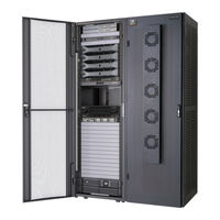
Vertiv Liebert XDC System Design Manual (200 pages)
Brand:
Vertiv
| Category:
Accessories
| Size: 41 MB
Table of Contents
Table of Contents
3
1 System Description
7
European Union Fluorinated Greenhouse Gas Requirements
7
Generic Piping Layouts
8
Liebert XDA-Air Flow Enhancer
9
Liebert XDCF-Liebert XD Coolframe
10
Liebert XDH-Horizontal Cooling Module
10
Liebert XDO-Overhead Cooling Module
11
Liebert XDR-Rear Cooling Module
13
Liebert XDV-Vertical, Above-Cabinet Cooling Module
13
Liebert XDC-Refrigerant Chiller
15
Liebert XDC Minimum Load
15
Liebert XDP-Pumping Unit
15
Liebert XDP Minimum Load
16
Liebert XD Piping
16
Liebert XD Field Piping
16
2 Starting a New Equipment Cooling Project
19
Determining Cooling Equipment Needs
19
Implementing a Hot-Aisle/Cold Aisle Design
19
3 Designing a Liebert XD Solution
21
Determine Cooling Requirements and Select Liebert XD System
21
Calculate the Heat Load to be Handled by Liebert XD System
21
Selecting Liebert XD Cooling Modules
22
Configuring a Liebert XD System
24
Number of Modules Supported by a Liebert XDP or Liebert XDC
24
System Connection Configuration
25
Airflow Requirements for Liebert XD Solutions
26
Liebert XDCF Placement
26
Liebert XDH Placement
27
Liebert XDO Placement
28
Determining Spacing of Liebert Xdos in an Aisle
28
Determining Vertical Placement of Liebert Xdos above the Cold Aisle
29
Liebert XDR Module Placement
30
Airflow
31
Liebert XDV Module Placement
32
Liebert Xdp/Liebert XDC Placement
33
Examples of Expansion and Interlaced Connection of Liebert XD Cooling Modules
34
Liebert XD Piping System Design
38
Liebert XD Piping Slope
40
Bypass Flow Controllers
40
Piping Details-Shutoff/Isolation Valves
42
Piping Details-Shutoff/Isolation Valves
43
Piping Details-Return Header Port Orientation
44
Piping Details-Bull Heading Layout
46
Piping Installation Method Prefabricated Headers
47
Liebert XD Flex Pipe Kit
54
Liebert XD Refrigerant
55
Determining Refrigerant Volume
56
Liebert Xdp/Liebert XDC Pumped R-134A Circuit Volume
56
Calculating Refrigerant R134A Charge-Example
57
Chilled Water Piping
58
Electrical
60
Temperature/Humidity Sensor Locations
60
Connecting Liebert XDP and Liebert XD Cooling Modules in a Canbus Network
60
Canbus Cables
60
Canbus Cable Length in a Network
61
Remote Sensor Placement Within the Canbus
62
4 Liebert XD Cooling Modules-Liebert XDCF, Liebert XDH, Liebert XDO, Liebert XDR and Liebert XDV
65
Liebert XDCF Standard Features
65
Liebert XDCF Mechanical Considerations
65
Liebert XDCF Installation Considerations
67
Liebert XDCF Piping Connection Methods and Points
67
Header System-Liebert XDCF
68
Liebert XDH Standard Features
68
Optional Features-Liebert XDH
69
Connecting High-Voltage Wiring-Liebert XDH
71
Connecting Low-Voltage Wiring-Liebert XDH Smart Modules
72
Liebert XDO Standard Features
73
Optional Features Liebert XDO
73
Low-Voltage Wiring-Liebert XDO Smart Modules
80
Liebert XDR Standard Features
81
Optional Features-Liebert XDR
81
Liebert XDR Installation Considerations
82
Liebert XDV Standard Features
86
Optional Features-Liebert XDV
87
High-Voltage Cabling for Liebert XDV
93
Low-Voltage Wiring-Liebert XDV Smart Modules
97
5 Liebert XDC and Liebert XDP
99
Liebert XDC Standard Features
99
Liebert XDC Optional Features
99
Liebert XDP Standard Features
109
6 Heat Rejection
117
Liebert Lee-Temp™ Refrigerant Control Air-Cooled Condensers
117
Liebert Lee-Temp Refrigerant Control Air-Cooled Condenser
117
Standard Features-All Condensers
117
Condenser Coil
118
Housing
118
Propeller Fan
118
Fan Motor
118
Electrical Controls
118
Mechanical Considerations
119
Dimensions
119
Heat Rejection Piping
123
Piping for Direct Expansion (DX) Circuit-R-407C Air-Cooled Units
123
Install Double Discharge Risers
123
Air-Cooled Condenser with Liebert Lee-Temp "Flooded Condenser" Head Pressure Control System-R-407C (DX) Circuit
133
Calculating Refrigerant Volume
133
Liebert XDC DX R-407C Circuit Volume
134
Liebert Drycoolers
135
Liebert Drycooler Fan Cycling Control
135
Pump Controls
135
Typical System Configurations
135
Site Considerations
136
Dimensions and Weights
137
Mounting the Drycooler
140
Glycol Piping
140
Piping Guidelines
140
Expansion Tanks, Fluid Relief Valves, Air Management and Other Devices
141
Electrical Supply
141
Line Voltage Wiring
142
Low Voltage Control Wiring
143
Filling Instructions
145
Preparing the System for Filling
145
Glycol Solutions
145
Filling the System
147
Outdoor Control Enclosure
147
Electrical Connections
149
Hazardous Voltage Power Supply Wiring
149
Extra-Low Voltage Control Wiring
150
Dual Pump Package Flow Switch
151
Dual Pump Controls Sequence of Operation
151
7 Liebert Icom
153
Liebert Icom Display Layout
153
Cooling Module Overview
155
Graphical Data Record
156
Liebert Icom User Menu Icons and Legend
156
Liebert Icom Service Menu Icons and Legend
157
Liebert XDC Alarms Descriptions
157
Warning Descriptions
161
Liebert XDP Alarms
161
Liebert XDP Warnings
164
Canbus Communications
164
Network Layout Options
165
Remote Temperature/Humidity Sensor Placement and Connection to the Canbus
165
Canbus Maximum Length
168
Canbus Cables
168
Connecting the Canbus Network
169
Connection to the Liebert XDP or Liebert XDC
169
Connecting to the Liebert XDV Smart Modules
171
Connecting to the Liebert XDH Smart Modules
172
Connecting to the Liebert XD Smart Modules
175
Canbus Termination
175
Remote Temperature and Humidity Sensors Termination
175
Terminating a Smart Module
176
8 Monitoring
177
9 Specifications and Model Number Nomenclature
183
Advertisement
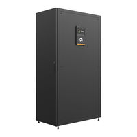
Vertiv Liebert XDC User Manual (132 pages)
50 & 60 Hz, 130 & 160kW Nominal Cooling Capacity Model Revision 5 or Higher
Brand:
Vertiv
| Category:
Freezer
| Size: 13 MB
Table of Contents
Table of Contents
3
1 Important Safety Instructions
5
2 Product Description
9
General Product Information
9
Product/System Description
9
Equipment Inspection
10
Equipment Handling
10
Handling the Liebert XDC While It Is on Skid and Packaged
10
Unpacking the Liebert XDC
11
Removing the Unit from the Skid Using a Forklift
11
Removing the Unit from the Skid Using Rigging
12
Moving the Liebert XDC Using Piano Jacks
13
Removing the Unit from the Piano Jacks
14
3 Installation
15
Mechanical Considerations
15
Positioning the Liebert XDC
15
Placing the Liebert XDC on a Floor Stand
17
Positioning the Liebert XDC with Floor Stand
20
Electrical Considerations
22
High Voltage Connections
22
Connecting High-Voltage Cables
23
External Pump Overloads
27
Extra Low Voltage Connections
28
Remote Sensor Installation-Proper Placement
34
4 Piping and Filling with Refrigerant: R-134A and R-407C Circuits
37
European Union Fluorinated Greenhouse Gas Requirements
37
Recommended Pipe Size
37
Liebert XDC Interconnection with Liebert XD Cooling Module
38
Piping Installation Method
38
Piping Installation-R-134A Pumped Circuit
39
Bypass Flow Controllers
39
Piping Details-Shutoff/Isolation Valves
41
Filling the Pumped Circuit-R-134A
41
Calculating Refrigerant Charge-Example
44
Piping for Direct Expansion (DX) Circuit-R-407C Air-Cooled Units
45
Install Double Discharge Risers
45
Air-Cooled Condenser with Liebert Lee-Temp "Flooded Condenser" Head Pressure Control System-R-407C (DX) Circuit
54
Filling the Direct Expansion (DX) Circuit-R-407C
55
System Refrigerant Charges over 55Lb. (24.9Kg) Require Additional Oil
57
Liebert XDC DX R-407C Circuit Volume
57
5 Installation Checklist
59
6 Liebert Icom Control-Firmware Version XP1.00.009.STD
61
Liebert Icom Components and Functions
61
Display Lamp Indicators
63
Navigating through the Liebert Icom Display
63
Accessing Menus and Settings
64
Cooling Module Overview
64
Entering the Password
65
Changing Liebert Icom's Display Settings
66
Changing Operational Settings
67
Graphical Data Record
67
Liebert Icom User Menu Icons and Legend
68
Liebert Icom User Menu Screens
69
Liebert Icom Service Menu Icons and Legend
79
Liebert Icom Service Menu Screens
80
7 Start the Liebert XDC with Liebert Icom
111
Checklist for Liebert XDC Startup
111
8 Alarm Descriptions and Solutions
115
Alarm Descriptions
115
Warning Descriptions
118
System Shutdown Causes
118
9 Troubleshooting
121
10 Maintenance
123
Fluorinated Greenhouse Gas Requirements
123
Air-Cooled Condenser
123
Water/Glycol Floor Stand Condenser
124
Shell and Tube Condensers
124
Regulating Valves
124
Glycol Solution Maintenance
124
11 Specifications
127
Vertiv Liebert XDC User Manual (70 pages)
High Heat Density Precision Air Conditioner
Brand:
Vertiv
| Category:
Air Conditioner
| Size: 9 MB
Table of Contents
Table of Contents
4
1 Overview
8
Product Introduction
8
Energy Saving
8
Diversified Terminal Types
9
Model Nomenclature
11
Product Appearance
12
Main Components
12
Compressor
12
Sight Glass
13
Color Display Screen
13
Safety Control Device
14
Oil Separator
14
Remote Monitoring Software
14
Outdoor Unit
14
Refrigerant Requirements
14
Environmental Requirements
15
Operating Environment
15
Storage Environment
15
2 Mechanical Installation
16
Equipment Room Requirements
16
Maintenance Space Requirements
16
Unpacking and Inspection
17
Transportation and Handling
17
Unpacking
18
Inspection
19
Installation Notes
19
System Installation Layout
20
Overall System Layout
20
System Installation Diagram
21
Installation of the Unit
22
Mechanical Parameters
22
Leveling the Cabinet
23
Removing Leveling Feet and Fixing Cabinet
24
Parallel Connecting Cabinets
26
Unit Piping Installation
27
Connecting Refrigeration Piping
27
Dimension Refrigerant Piping
29
Branch Manifold
31
Connecting Refrigerant Piping
32
Air Tightness Test
33
Charging Refrigerant Oil
33
Remove Transportation Fixing Plate of Compressor
35
Mechanical Installation Checklist
36
3 Electrical Installation
37
Installation Tasks and Cautions
37
Cabling Connection at the Site
37
Installation Notes
37
Cabling of the Unit
38
Electrical Interface Location of the Unit
38
Connection of Unit Power Supply Cables
39
Control Cables Connections
40
Electrical Inspection Checklist
42
4 System Startup and Commissioning
43
Startup and Commissioning
43
Preparation before Commissioning
43
Vacuuming
43
MCB Position
44
Static Refrigerant Charge
44
Dynamic Refrigerant Charging
44
Commissioning Inspection Checklist
45
5 Color Display Screen Operating Instructions
46
Features
46
Appearance
46
Color Screen Interface
47
Startup Interface
47
Main Interface of the Color Screen
47
Operation Example
49
Other Interfaces
50
Alarm Status
50
Main Unit Menu
51
Terminal Menu
52
Run Time
53
About
54
6 System Operation and Maintenance
55
Routine Maintenance Inspection (Monthly)
55
Routine Maintenance Inspection (Semi-Annual)
56
System Troubleshooting Test
57
Electrical Connection Inspection
57
Electrical Maintenance
57
Control Maintenance
57
Cooling System
58
Suction Pressure
58
Exhaust Pressure
58
Terminal Electronic Expansion Valve
58
Terminal Fan
59
Air-Cooled Condenser
59
Compressor
59
Mechanical Failure
60
Electrical Failure
60
7 Troubleshooting
61
Appendix I: Circuit Diagram of Vertiv™ Liebert® XDC
64
Appendix II: Alarm Output Menu
65
Appendix III: Hazardous Substance Content
66
Appendix IV: List of Maintenance Inspection Items (Semi-Annual)
67
Appendix V: Toxic and Hazardous Substances or Elements
68
Advertisement
Advertisement
Related Products
Vertiv Liebert DSE
Vertiv Liebert HPW Series
Vertiv Liebert HPM
Vertiv Liebert XDP Series
Vertiv Liebert PDX Series
Vertiv Liebert XD Series
Vertiv Liebert XDA
Vertiv Liebert XDCF
Vertiv Liebert XDH
Vertiv Liebert XDO
Vertiv Categories
UPS
Power Supply
Switch
Power distribution unit
Air Conditioner
More Vertiv Manuals
Login
Sign In
OR
Sign in with Facebook
Sign in with Google
Upload manual
Upload from disk
Upload from URL