Table of Contents
Advertisement
Quick Links
Advertisement
Table of Contents

Related Manuals for Labnet Spectrafuge 16M


Summary of Contents for Labnet Spectrafuge 16M
- Page 1 SERVICE MANUAL LABNET SPECTRAFUGE 16M MICROCENTRIFUGE...
-
Page 2: Table Of Contents
Contents Section 1 General Description of Operation ............1 Specifications ................... 2 Section 2 Warranty Information ................3 Section 3 Troubleshooting ..................4 Section 4 Service Instructions ................. 5 Maintenance ................. 5 Cleaning and lubrication Removing the rotor Maintaining the rotor Rotor screw Speed Calibration Service Procedures .............. -
Page 3: General Description Of Operation
Section 1 General Description of Operation This centrifuge is generally used in biological and biochemical research laboratories where small samples must be subjected to high RCF (g-force) for relatively short time intervals (usually thirty min- utes or less). Designed to accept popular micro-test tubes with captive caps in a high speed rotor, this centrifuge will provide centrifugal forces as high as 16,000 times the power of the earth's gravity (16,000 x g)* The major functional components of the centrifuge are as follows: Motor... -
Page 4: Specifications
Section 1 Specifications Maximum speed ....................14,000 rpm ±5% Maximum RCF ......................16,000 x g Maximum capacity ..................36 mL (18 x 2.0 mL) Dimensions Width ....................209.5mm/8.25 in. Depth ....................226mm/8.9 in. Height ....................193mm/7.6 in. Weight ....................5.1kg/11.2 lbs. Noise level (with full rotor) .................. -
Page 5: Warranty Information
FITNESS FOR A PARTICULAR PURPOSE ARE LIMITED IN DURATION TO 12 MONTHS FROM THE DATE OF ORIGINAL PURCHASE. REPAIR OR REPLACEMENT IS PROVIDED AS THE SOLE AND EXCLUSIVE REMEDY. NATIONAL LABNET COMPANY IS NOT LIABLE FOR INCIDENTAL OR CONSEQUENTIAL DAMAGE, COMMERCIAL LOSS, OR ANY OTHER LOSS OR DAMAGE NOT SPECIFIED IN THIS WARRANTY. -
Page 6: Troubleshooting
Section 3 Troubleshooting Problem Possible cause Solution Lid will not open Rotor still turning. Wait for rotor to stop. (with power/rotation light on). Internal electrical failure. Requires service. Lid will not open No power supply. Check plug connection on back of unit. (with power/rotation light off). -
Page 7: Service Instructions
Section 4 Service Instructions MAINTENANCE Beginning after the first 300 hours of use, and periodically thereafter, a qualified electronics technician should inspect the centrifuge. Cleaning & Lubrication The rotor, rotor chamber and centrifuge casing must be kept clean. Using a cloth damp with water or mild detergent, the casing and chamber should be wiped clean and kept in "like- new"... -
Page 8: Rotor Screw
Section 4 Rotor screw The rotor screw must be kept tight enough that it cannot be removed by hand. If it has become loose, tighten it firmly, clockwise, by hand and subsequently torque an additional 1/8 turn using a wrench or other appropriate tool. Speed calibration After every 100 hours of use (or more frequently if required by other agencies) the maximum rotor speed should be... -
Page 9: Service Procedures
Section 4 9) Adjust the low speed pot (front-most) so that the rotor speed measures 1,000rpm, plus or minus 100rpm on the tachometer. 10) Replace the metal chute The unit is now calibrated. SERVICE PROCEDURES Take care when performing the following service procedures. Always disconnect the unit from power source before attempting any service operations. -
Page 10: Printed Circuit Board
Section 4 2) Unplug the motor connection from the PCB. 3) Loosen the ground nut and remove the motor ground lead (figure #4, pg 14). 4) Remove the 4 motor nuts on the bottom of the base- plate (figure #5, pg 15). Remove motor assembly and 4 star washers under the isolators from unit, noting the orientation and routing of motor and ground leads. -
Page 11: Miscellaneous Components
Section 4 2) From the bottom of the unit, remove the 2 PCB mount- ing screws and nuts that secure the PCB brackets to the baseplate (see figure #6, pg 16). 3) One at a time, remove each of the 3 plug in connectors from the old PCB and install into the same location on the new PCB. - Page 12 Section 4 After removing, turn the upper casing so that the inside of the front panel is visible (figure #7, pg 17). If power to the solenoid is present, but the solenoid does not move, it should be checked and/or replaced. Other potential latch faults could be the result of poor wiring connections, poor alignment of the lid latch catch, sticking or jamming of the lid latch strike or no contact at the...
-
Page 13: Illustrations
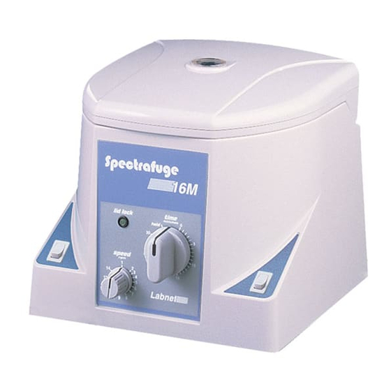
Section 5 Illustrations Figure 1 Spectrafuge 16M Tach window Upper casing switch Timer Quick button Speed control Lid lock indicator... - Page 14 Figure 2 Position of screws holding upper casing to baseplate (shown from bottom of unit) Casing-baseplate screw Casing-baseplate screw Casing-baseplate screw Casing-baseplate screw...
- Page 15 Figure 3 Position of metal chute and attachment screws (view from bottom of unit) Metal chute with screws at the 4 corners...
- Page 16 Figure 4 Location of motor and motor ground nut Motor Motor ground nut...
- Page 17 Figure 5 Location of nuts holding motor in place (bottom view of unit) Motor nuts...
- Page 18 Figure 6 Location of PCB and its mounts PCB mounts...
- Page 19 Figure 7 View of front control panel electronics Underside of front control panel...
- Page 20 Figure 8 Location of transformer and transformer mounts Transformer mounts Transformer...
-
Page 21: Spare Parts List
Section 6 Spare Parts Catalog # Description Price C0160-CB Circuit board $270.00 C0160-E Motor, complete 295.00 C-0160-F Feet, set of 4 12.00 C0160-FUSE Fuse, 2.5amp (120V version) 1.75 C0160-FUSE1 Fuse, 1.25amp (230V version) 1.75 C0160-I Isolator 3.00 C0160-LB Centrifuge lid, Blue 80.00 C0160-LG Centrifuge lid, Grey... -
Page 22: Schematics And Drawings
Section 7 Schematics and drawings This page intentionally left blank... - Page 23 Wiring Diagram - 120V...
- Page 24 Wiring Diagram - 230V...
- Page 27 Control Board Reference Reference Part C1, C9, C19, C20 NIC NRSA 100 M 35V 5X11 TR C2, C4, C6, C7, C8, C10, C18 NIC NCMA10 Z5U 103 M 100 TR C3, C14, C16, C17 NIC NCMA30 Z5U 105 M 50 TR NIC NCMA20 Z5U 104 M 50 TR NIC NRSA 222 50V 18X36 TR NIC NRSA 101 50V 8X11.5 TR...
- Page 28 Control Board Reference - continued Reference Part SAFTY1 HEADER 4 PIN NOT USED SOLENOID1 LID OPEN SOLENOID 24 VAC SPEED1 FRONT PANEL POT 100K TRANSFORMER TIMER1 FRONT PANEL TIMER SW. ATF16V8BQL-25PC LM7815T LM339CN LM7805T ULN2003N LM555CN MOC3010 MAX954EPA CD4093BCN WH1, WH2, WH3, WH4...
Need help?
Do you have a question about the Spectrafuge 16M and is the answer not in the manual?
Questions and answers