
Subscribe to Our Youtube Channel
Related Manuals for Finn Bark Blower BB-200


Summary of Contents for Finn Bark Blower BB-200
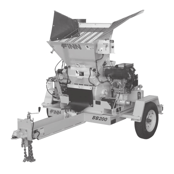
- Page 1 9281 LeSaint Drive • Fairfield, Ohio 45014 Phone (513) 874-2818 • Fax (513) 874-2914 Sales: 1-800-543-7166 Model BB-200 Parts and Operator’s Manual Model SE Serial No. ___________ LBBB200-SE...
-
Page 3: Table Of Contents
OPERATION AND MAINTENANCE......6-20 The FINN Bark Blower and Its Function ..... . . 6 How the Bark Blower Works . - Page 4 INDEX CONTINUED Notes ........... 20 PARTS MANUAL .
-
Page 5: Safety First
SAFETY FIRST With any piece of equipment, new or used, the most important part of its operation is SAFETY! Finn Corporation encourages you and your employees to familiarize yourselves with your new equipment and to stress safe operation. The first six pages of this manual are a summary of all the main safety aspects associated with this unit. -
Page 6: Bark Blower Safety Summary Section
BARK BLOWER SAFETY SUMMARY SECTION It is important that all operators of this machine are familiar with all the safety aspects mentioned below before operating the machine. Always keep a copy of this manual with the machine. It is the responsibility of the operator of the machine to fully understand this safety section. - Page 7 10. Never modify the machine. Never remove any part 16. Do not read, eat or otherwise lose or lessen your of the machine (except for service and then reinstall attention in any manner while operating the blower. before operating). Operating is a full time job. 11.
- Page 8 It is recommended that only authorized genuine container whose contents or previous contents are FINN replacement parts be used on this machine. unknown. Do not use ether cold start fluid if engine is equipped with glow plug type preheater or other intake mani- fold type preheater.
-
Page 9: Current Set Of Safety Decals
CURRENT SET OF SAFETY DECALS DA NG E R S E V E R H A Z A R D ! WA R NING K eep hands and feet out! B U R N H A Z A R D ! S harp knives will s ever. -
Page 10: Operation And Maintenance
TOWING VEHICLE: The truck used to tow the FINN Model BB-200 Bark Blower must be equipped with the appropriate ball or pintle type hitch. This hitch should be mounted as near to the end of the truck bed as possible. The tow vehicle should be fully wired for trailer marker, turn, and stop lights as well as electric brakes. -
Page 11: Pre-Start Equipment Check
The mulch material must be processed and/or screened so that a minimum of material is over 2 inches (5.1 cm) in any direction with no material exceeding 3 inches (7.62 cm) in length. The Bark Blower is not a wood processor. -
Page 12: Starting Procedure
6. Allow the engine to warm up for three to five minutes. 7. Prior to mulch application, move the throttle position to fully open, and allow the governor to con- trol the engine speed. Governed engine speed on the FINN Bark Blower should be 3300 to 3600 RPM under load. -
Page 13: Subsystem 2: Hydraulic System
The Feed Rolls receive material from the hopper and meters it to the Rotary Air Valve. They insure a uni- form feed of bulk material to the Rotary Air Valve, and are powered by a variable speed hydraulic motor connected together by a chain drive. The Rotary Air Valve receives the material from the Feed Rolls and pressurized air from the Blower. -
Page 14: Subsystem 3: Hydraulic Control System
Decrease Increase Black Cartridge with 1" (25mm) Diameter Knob: Turn Counter-Clockwise to Increase Speed. Turn Clockwise to Decrease Speed. Figure 1 - Flow Control Valve SUBSYSTEM 3: HYDRAULIC CONTROL SYSTEM The hydraulic control system is an electrical system that controls the on-off function of the feed roll motor and the rotation direction of the rotary air valve motor. -
Page 15: Mulching With The Bark Blower
MULCHING WITH THE BARK BLOWER: 1. Check all areas listed under “Pre-Start Equipment Check” (pages 7). 2. Start the engine following all the steps listed under “Starting Procedure” (page 8). 3. Set the floor speed control to ½ to 1 turn from minimum. 4. -
Page 16: Electronic Timer Range Programming Instructions
TROUBLE SHOOTING CHART CONT'D: Symptom Probable Cause Remedy Air valve motor stalls Reverse time interval too Reset timer (1 sec.) in forward, no auto short. (TR1) reverse. Knives dulled or chipped: Sharpen blades, Knife clearance too large. reset knife clearance. Relief pressure on solenoid Reset to 2100 psi. -
Page 17: Select Time Range
ELECTRONIC TIMER SELECTOR MODE A = Delay DESIGNATOR B = Interval C = Not Used FLAT D = Not Used SCREWDRIVER Figure 3 - Set Mode of Operation DIAL SETTINGS SELECT THE TIME RANGE Select the time range by turning the scale selector until the appropriate dial settings appear on the timer faceplate. -
Page 18: Cleaning And Maintenance
Range DIAL SETTINGS Designator 0-10 0-30 0-60 0.1 Sec. - 1 Sec. 0.1 Sec. - 3 Sec. 0.2 Sec. - 10 Sec. 0.6 Sec. - 30 Sec. 1.2 Sec. - 60 Sec. 1.2 Sec. - 1 Min. 3.6 Sec. - 30 Min. 12 Sec. -
Page 19: Weekly After Every 50 Hours Of Operation
2. Retorque wheel lugs 85-98 ft. lbs. (12-13 kg-m) after 7 days. (Trailer option only). 3. Change the engine oil and filter. CAUTION: Adjust only while the engine is off. WEEKLY - AFTER EVERY 50 HOURS OF OPERATION: 1. Lubricate the bearings on the blower and on each end of the feed roll shaft. Wipe each bearing before lubrication to remove dirt and prevent overheating. -
Page 20: After First 100 Hours Of Operation
i) Remove the wood block, and check the clearance between the knife and the rotor vane using a feeler gauge at the three mounting bolts. NOTE: If the knife touches the vane at any point, loosen the three mounting bolts, back off the jacking screws evenly, and repeat steps g, h, and i until clearance is obtained. -
Page 21: Every 3 Months Or 3000 Miles (4800 Km)
EVERY 3 MONTHS OR 3000 MILES (4800 KM): 1. Check and adjust trailer brakes. 2. Re-torque wheel lug nuts (85-95 ft.lbs. (12-13 kg-m)). 3. Check tire condition. EVERY 12 MONTHS OR 12000 MILES (19300 KM): 1. Inspect and repack wheel bearings. 2. -
Page 23: Lubrication Chart
LUBRICATION CHART Ref. No. Location Lubricant Frequency Number Feed Roll Bearing (Idle & Drive) Weekly Blower Bearings Weekly Airlock Bearing Daily Tire Air Pressure Weekly Wheel Bearings Annually Check Oil Level - Blower Daily Change Oil - Blower Annually Check Fuel Level Daily Check Hydraulic Oil Level Daily... -
Page 24: Notes
NOTES... -
Page 25: Parts Manual
BARK BLOWER Model BB-200 Parts Manual Model SE LBBB200-SE... -
Page 26: Notes
NOTES... -
Page 27: Trailer And Carriage Assemblies
FINN BB-200 BARK BLOWER HOPPER See Pages 32-33 DRIVE COMPONENTS See Pages 34-35 ENGINE AND CONTROL BOX WIRING See Pages 40-41 FEEDER PARTS See Pages 30-31 BLOWER COMPONENTS See Pages 36-37 HYDRAULIC PARTS See Pages 38-39 AIRLOCK ASSEMBLY See Pages 28-29... - Page 28 REF: AXLE AND HUB PARTS (SEE PAGE 26) REF: BRAKE ASSEMBLIES (SEE PAGE 27) WHEN ORDERING PARTS, BE SURE TO STATE SERIAL NUMBER OF MACHINE LBBB200-SE...
- Page 29 TRAILER AND CARRIAGE ASSEMBLIES Ref. No. Part Number Description No. Req’d 340030 Trailer Weldment 340034-02 Carriage Clamp - LH 340035 Rear Carriage Weldment 340034-01 Carriage Clamp - RH F201-0008 Rear Fender Mount F201-0007 Fender 005545 Square U-Bolt 005436 License Light 004720 License Plate Bracket 340034-17...
- Page 30 AXLE & HUB PARTS Ref. No. Part Number Description No. Req’d 055736 Axle Assembly WL10-9 Grease Seal WL31-31-2 Inner Bearing Cone WL31-31-1 Inner Bearing Cup WL31-31-1 Outer Bearing Cup WL31-31-2 Outer Bearing Cone WL6-1 Spindle Nut WL21-3 Grease Cap WL19-2 Cotter Pin WL8-247-5 Hub &...
- Page 31 BRAKE ASSEMBLIES Ref. No. Part Number Description No. Req’d WL23-26 Left-Hand Brake Assembly WL23-27 Right-Hand Brake Assembly WL36-19-10 Backing Plate Assembly WL47-19 Left-Hand Actuating Lever Arm WL47-20 Right-Hand Actuating Lever Arm WL05-067 Washer WL27-5 Wire Clip WL46-9 Retractor Spring WL71-47 Shoe &...
- Page 32 NOTE: ITEM #1 (AIR LOCK ASSEMBLY) INCLUDES ITEMS #2 - #26 WHEN ORDERING PARTS, BE SURE TO STATE SERIAL NUMBER OF MACHINE LBBB200-SE...
- Page 33 AIRLOCK ASSEMBLY Ref. No. Part Number Description No. Req’d 340060 BB200 Airlock Assembly 055552 Hydraulic Motor 052139-03 Gearbox Spacer 055700 Excluder Slinger Seal 055439-02 Inlet End Plate 055721 Inlet Seal End Plate 055148-01 Rotor Housing Shim - 1/32" Thick 055148-02 Rotor Housing Shim - 1/16"...
- Page 34 REF: HOPPER See Pages 32-33 REF: AIRLOCK ASSEMBLY See Pages 28-29 NOTE: FRONT AND RH SIDE OF HOPPER NOT SHOWN FOR CLARITY. WHEN ORDERING PARTS, BE SURE TO STATE SERIAL NUMBER OF MACHINE LBBB200-SE...
- Page 35 FEEDER PARTS Ref. No. Part Number Description No. Req’d F201-0022 Mount Strap 035123 Plastic Fuel Tank 340033 Fuel Tank Mount Weldment F201-0046 Fuel Tank Shield 340036 Feed Wheel Weldment 340026-01 Driven Shaft 340026-02 Drive Shaft 340024 Bearing 340020 Sprocket 080482 Hydraulic Motor F201-0035 Lower Chain Guard...
- Page 36 DETAIL B DETAIL A DETAIL C DETAIL A WHEN ORDERING PARTS, BE SURE TO STATE SERIAL NUMBER OF MACHINE LBBB200-SE...
- Page 37 HOPPER Ref. No. Part Number Description No. Req’d F201-0030 Wedge F201-0028 Hopper Top Side - L.H. 340029-08 Rubber Mounting Angle 340029-12 Hopper Flap 340029-10 Swing Bolt Mount - L.H. Side 340050 Front Door Weldment F201-0029 Hopper Front F201-0026 Roll Side - L.H. 340029-09 Swing Bolt Mount - R.H.
- Page 38 WHEN ORDERING PARTS, BE SURE TO STATE SERIAL NUMBER OF MACHINE LBBB200-SE...
- Page 39 DRIVE COMPONENTS Ref. No. Part Number Description No. Req’d 340017 Belt Tensioner Stud 055486 Shaft Tensioner 340057 Belt Tensioner Mount 340058 Belt Tensioner Base 055706 Blower 340029-05 Belt Guard Spacer 340029-04 Hydraulic Filter Mount 340029-01 Blower Mounting Angle F201-0011 Front Belt Guard 340007 Blower Sheave 340004...
- Page 40 WHEN ORDERING PARTS, BE SURE TO STATE SERIAL NUMBER OF MACHINE LBBB200-SE...
- Page 41 BLOWER COMPONENTS Ref. No. Part Number Description No. Req’d 340011 Air Filter 055335 4" Clamp 075245 4" x 3" Reducer 340037 Cowl Silencer 055501 Muffler Clamp 055584-06 Blower Filter Adapter 055706 Blower 055496 3" Clamp 340014 Hump Reducer 340002 Cowl Silencer 340013 Insert Sleeve 055497...
- Page 42 WHEN ORDERING PARTS, BE SURE TO STATE SERIAL NUMBER OF MACHINE LBBB200-SE...
- Page 43 HYDRAULIC PARTS Ref. No. Part Number Description No. Req’d 004900 Filler Pressure Breather Cap 340028-10 Hydraulic Tank (Part of Frame) 340009 Strainer 340039 Hydraulic Fitting 340043 Hydraulic Hose 20" Long FW65224 Straight Adpater 340003 Hydraulic Pump FW65217 Straight Adapter FW71909 90 Degree Elbow 340046 Hydraulic Hose 53"...
- Page 44 IGNITION SWITCH “B” “M” “M” ORANGE/BLACK MODE TIMER SOCKET “S” “A” SET TO SCALE ROLL DELAY RED/BLACK RANGE TIMER BLACK/RED YELLOW/BLACK 16 GA. YELLOW BROWN/BLACK YELLOW 16 GA. BROWN ORANGE TOGGLE SWITCH MODE 16 GA. BLACK AUTO REVERSE YELLOW ON/OFF SET TO SCALE TIMER...
- Page 45 ENGINE AND CONTROL BOX WIRING Part Number Description No. Req’d 340064 Control Box Assembly 340051 Control Box 052112 Toggle Switch - SPST 080526 Switch Boot 080654 Ignition Switch FW71584 Timer Relay FW71585 Timer Relay Socket 006245 Red Pilot Light 340070 Control Box Wiring Harness 035078 Connector...
-
Page 46: Trailer Wiring
LICENSE LIGHT Brown Brown Yellow Brown TRAILER PLUG LEFT TAILLIGHT White BREAKAWAY SWITCH STARTER Green Brown Brown FEMALE COUPLER RUNNING LIGHTS (Looking at Terminal End) (Brown) RIGHT TAILLIGHT White ENGINE BATTERY GROUND RIGHT TURN LEFT TURN (Green) (Yellow) ELECTRIC BRAKES GROUND (Black) (White) - Page 47 TOOL KIT AND DISHARGE HOSE Part Number Description No. Req'd 012681A Touch-Up Paint (FINN Beige - 4.5 oz. Aerosol) 012681T Touch-Up Paint (FINN Beige - 0.5 oz. Wet) Engine Operators Manual Blower Operators Manual LBBB200-SE Bark Blower BB-200 Parts & Operators Manual...
- Page 48 WHEN ORDERING PARTS, BE SURE TO STATE SERIAL NUMBER OF MACHINE LBBB200-SE...
-
Page 49: Decal And Plate Locations
Decal "DANGER . . . Rotating Parts" 023857 Decal "CAUTION . . . Wear Hearing Protection" 052178 Decal "IMPORTANT . . . If Machine Is To Remain On" 071097 Decal "FINN" (Small/Red) 340062 Decal "BB200" KL2411303 Decal "Ignition Switch" 007535 Decal "Throttle"... -
Page 50: Warranty
Finn to verify said nonconformity and verify the continuing existence of the warranty period, Finn will provide a new part or a repaired part, whichever Finn elects, to replace the part found to be defective. Such parts will be provided without charge to the Purchaser during normal working hours at a place of business of a Finn dealer or other establishment authorized by Finn to effect said repairs or replacements, but Purchaser shall bear all costs of transporting the product to and from such place of business or establishment.
Need help?
Do you have a question about the Bark Blower BB-200 and is the answer not in the manual?
Questions and answers