Table of Contents
Advertisement
Quick Links
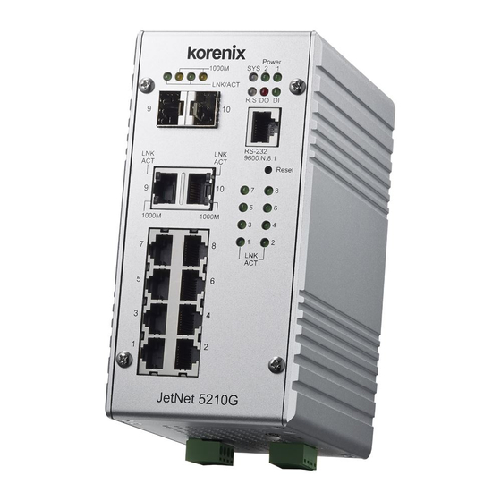
JetNet 5210G Industrial 8+2 Gigabit RJ/SFP DIN Rail Managed Switch
Quick Installation Guide V1.0
Ethernet Switch, which designed with eight 10/100TX ports and two Gigabit RJ-45 / SFP
combo ports. It is designed for field site data convergence to backbone network and up to
control data center. The highly heavy industrial Electric-Magnetic Compatibility level, wide
operating temperature and voltage provides excellent environmental tolerance to bear the
applications which are installed in out-door or the environment with high noise interference,
such as factory, railway track-site or Intelligent Traffic Control System (I.T.C.S.). It also adopts
comprehensive network control protocols to enhance network transport performance. with
those brilliant system design and network features, the JetNet 5210G will be the best network
transmission device for your industrial Ethernet Switch solution.
Package Check List
JetNet 5210G with DIN Rail clip
Console Cable (RJ-45/DB9)
Quick Installation Guide
Installation
Interface Introduction
JetNet 5210G includes 10/100Mbps Fast Ethernet ports, SFP slot, RS232 console port, Reset
button and LEDs for system and port indication.
Dimension:
JetNet 5210G : 80 x 160 x 136 mm (W x H x D), with DIN Rail Clip
Mounting the unit
Mount the din-rail clip on the rear of JetNet 5210G on the DIN rail.
Wiring the Power Inputs & Earth Grounding
1. Insert the positive and negative wires into the V+ and V- contact on the terminal block
connector.
2. Connect the Chassis
Grounding to Earth Ground
system to obtain electromagnetic
immunity to resist lighting,
electro static discharge and
electric fast transient.
3. Tighten the wire-clamp
screws to prevent the power wires from being loosened.
Wiring the Relay Output
The relay output contacts are
in the bottom side. The relay
output (DO) is controlled by
the pre-defined operating
rules. To activate relay output
function, please refer to the
User's Manual for more relay output management information.
Notes: The relay contact only supports 0.5A current, DC 24V. It is not recommended to apply
voltage and current higher than the specifications.
Wiring the Digital Input
The Digital Input (DI) contacts are in
the bottom of the device. It accepts one
external DC type signal input and can
be configured to send alert message
through Ethernet when the signal is
changed.
Note: The DI accepts DC type signal
and supports isolated input circuit with Digital High Level input DC 11V~30V and Digital Low
Level input DC 0V~10V. Do not apply voltage higher than the specification; it may cause
internal circuit damage or a wrong action of DI.
Connecting the Surge / Lighting protection
The surge protection activate screw located on the
rear side under the DIN rail.Always tighten the
screw and ensure the Chassis-Grounding screw is
connected with Earth-Ground well.
Note: 1. Ensure the Surge/Lighting is
well connecting with Chassis Grounding.
2. Remove the Surge/Lighting Screw before
perform insulation/Hi-pot testing.
3. Never install or work on/with the equipment
or the cabling during the period of its lightning activity.
Device Management
You can configure JetNet 5210G via the RS-232 console with the attached console cable. Or
you can remotely manage the switch via network. You can choose Telnet/SSH,
Web/HTTPS management.
Preparation for console management
Attach the RS-232 DB9 connector to your PC's COM port. Connect the RJ-45 connector to
the console port of the JetNet Switch.
1. Go to Start ► Program ► Accessories ► Communication ► Hyper Terminal
2. Give a name to the new console connection.
3. Choose the COM name and select the correct serial settings. The serial port settings are as
below: Baud Rate:9600/Parity: None/Data Bit: 8/Stop Bit: 1
4. After connected, you will see the Switch login request. Type the username and password
and then you can login. The default username is "admin", password is "admin".
5. Follow the manual to configure the software features.
Preparation for Web management
1. Launch the web browser on the PC.
2. Type http://JetNet Managed Switch_IP_Address (The default IP address is 192.168.10.1.),
then press Enter.
3. The login screen will appear. Type in the user name and password and click "OK" button.
The default user name and password is admin/admin.
4. At the left column of the web management interface are the software features, where ring
column will list the available settings.
Support
5 Years Warranty
Each of Korenix's product is designed, produced, and tested with high industrial standard.
Korenix warrants that the product(s) shall be free from defects in materials and workmanship
for a period of five (5) years from the date of delivery provided that the product was properly
installed and used.
This warranty is voided if defects, malfunctions or failures of the warranted product are
caused by damage resulting from force measure (such as floods, fire, etc.), other external
forces such as power disturbances, over spec power input, or incorrect cabling; or the
warranted product is misused, abused, or operated, altered and repaired in an unauthorized
or improper way.
Attention! To avoid system damage caused by sparks, please DO NOT plug in power
connector when power is on.
The product is in compliance with Directive 2002/95/EC and 2011/65/EU of the European
Parliament and of the Council of 27 January 2003 on the restriction of the use of certain
hazardous substances in electrical and electronics equipment (RoHS Directives & RoHS 2.0)
Korenix Customer Service
KorenixCARE is Korenix Technology's global service center, where our professional staffs
are ready to answer your questions at any time.
Email address of Korenix Global Service Center : KoreCARE@korenix.com
Advertisement
Table of Contents

Related Manuals for Korenix JetNet 5210G


Summary of Contents for Korenix JetNet 5210G
- Page 1 (5) years from the date of delivery provided that the product was properly through Ethernet when the signal is JetNet 5210G : 80 x 160 x 136 mm (W x H x D), with DIN Rail Clip ...
- Page 2 良而导致产品故障,我们提供免费维修服务。 界面介绍 ,比如开门触发开关控制柜。 自然外力 (火、水、雷灾)所造成的产品故障,或其它外部因素如电源干扰、不 JetNet5210G 包括10/100Mbps的快速以太网端口,SFP插槽,RS232控制端口,Reset 注意: DI接受DC型信号隔离输 当电源输入、不当接线等造成的损坏,不列入产品保固范围;此外,产品被误用 按键和LED系统和端口指示。 入电路,并支持使用数字高电平输入直流11V〜30V和数字低电平输入DC0V〜10V 尺寸: 、未经授权的修理及修改等行为将造成保固条款失效。 。请不要使用超过规格的电压,它可能会造成内部电路损坏或造成DI行为错误。 JetNet 5210G :95 x 160 x 136.2mm (宽x高 x深),含轨道夹扣 轨道安装 注意! 请勿于电源开启时插拔接线端子,避免产生火花造成系统损坏。 连接电涌保护 该导轨卡夹已经收紧锁定在后侧面板,请采用并支持EN50022标准的工业轨道以便 此产品保证完全符合欧盟2003年1月27日电气和电子设备危害物质限制委员会限 电涌保护激活螺丝位于后侧导轨卡夹下方。务必拧紧螺丝,确保机箱-接地螺丝与大 安装交换机。 地系统接地连接以便取得良好的浪涌雷击保护。 用指令2002/95/EC (RoHS)及2011/65/EU(RoHS 2.0)。 Korenix客戶服务 注意: KoreCARE是科洛理思科技全球服务中心,我们专业的技术人员随时准备解答您的...
Need help?
Do you have a question about the JetNet 5210G and is the answer not in the manual?
Questions and answers