Advertisement
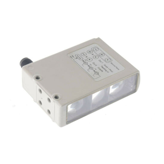
Harsh environment long distance photoelectric Sensor in metal housing
E3NT
• 4 Diffuse reflective E3NT-L application
optimized models:
• Extra long distance type for setting
distances up to 3 m
• Window heating type for low tem-
perature environments
• Analog output type for distance in-
formation
• Fast response type for high speed
detection and counting
• Retro reflective E3NT-R models with
sensing distance up to 16 m
• Two programmable outputs for 'win-
dow teaching'
• Double triangulation for stable detec-
tion of reflective objects
• IP67 and IP69k for highest resistance
in wet environments
Condensation in often cleaned envi-
ronments or due to rapid temperature
changes is prevented by the complete-
ly sealed housing of the E3NT and the
optional window heating.
E3NT
Application
With the optic link, the sensor can be
remotely set and checked while it is op-
erating in an area where access is re-
stricted.
This robust sensor is ideal for opera-
tion in harshest environments.
A-83
Advertisement
Table of Contents

Related Manuals for Omron E3NT


Summary of Contents for Omron E3NT
- Page 1 Harsh environment long distance photoelectric Sensor in metal housing E3NT • 4 Diffuse reflective E3NT-L application optimized models: • Extra long distance type for setting distances up to 3 m • Window heating type for low tem- perature environments • Analog output type for distance in- formation •...
-
Page 2: Ordering Information
Type Appearance Connection Sensing / Setting distance Model method Distance setting Long distance M12 Connector 0.2 m .. 3.0 m (90% remission) E3NT-L17-20 (BGS/FGS) (5-pole) 0.2 m .. 2.7 m (6% remission) 200 mm 3,000 mm E3NT-L37-20 Window heating 0.2 m .. 2.0 m... - Page 3 Mounting brackets Appearance Model Qty. Remarks E39-EL1 Universal mounting bracket E39-EL2 Adapter bracket (for use of the universal mounting bracket for not matching holes) E39-EL3 Adapter bracket replacing E3N with E3NT Reflectors E39-R8 f or M3 for M3 Sensor I/O connectors...
- Page 4 Signal evaluation Double triangulation method Polarization Configuration By push button on the sensor or with a PC connected via the optical data link E3NT-AL232 Operating modes Background suppression, foreground suppression, background and foreground suppression (2-point window evaluation) Light source...
- Page 5 Seals RTV silicone Housing color Grey, RAL 7030 Assembly Screw fastening by way of four M5 threads and two M5 through holes or with universal mounting bracket (order separately) Connection M12 connector, 5-pole (piercing) Ambient temperature range - 25 °C ... + - 10 °C ...
- Page 6 Item Supply voltage 3 V DC Battery type Button battery Ø 11.6 mm, thickness: 5.4 mm, 3 Vm, type: CR1/3N Ambient temperature range + 10 °C ... + 40 °C Storage temperature range - 40 °C ... + 60 °C (with no icing or condensation) Ambient humidity Operation and storage: 35% ...
- Page 7 Analog output current (90% remission) 1000 1500 2000 2500 Distance Z (mm) E3NT-L17-20 and E3NT-L37-20 Parallel Operating range Black/White - Error Hysteresis (typical) (6% - 90% remission, typical) Black White E3NT 1500 3000 3000 3000 Distance Z (mm) E3NT-R Spotsize...
-
Page 8: Circuit Diagram
0 V 3 When use is made of the PNP or NPN output circuit, the output circuit that is not selected is deactivated. When used as a comple- mentary output, NPN or PNP outputs act in antiphase as the switch state changes. -
Page 9: Operation
4-digit 7-segment LED display. The display appears as red digits or letters. If the sensor is set to a bar chart display, the distance from the measured object is displayed as a green LED bar chart. The switching status and the stability of the two outputs are signalled as follows by two LEDs, visible from... -
Page 10: Teach Menu
1.) In the 2-point window evaluation mode, two switching points (A/B and C/D) can be set for each output. In the foreground and background suppression modes, only one switching point (A and C) can be set for each output. Then, only these switching points, A and C, can be set in the TEACH menu path. B and D switching points are not available. - Page 11 Enter 2 s 1.) If connector pin 2 is set as an input, the switch-on/off delay function canonly be set for Output 1. A second switching output is not available. 2.) If the switch-on/off delay is off in the OPTIONS menu path, the switch-on/off delay parameters do not appear in the SET menu path.
-
Page 12: Options Menu
1.) If connector pin 2 is set as an input, the type of switch-on/off delay option can only be set for Output 1. 2.) If the ECO energy saving mode is on, the display is switched off if no keys are pressed for about 5 minutes. The display is switched on again when any key is pressed. - Page 13 Switch-on Set time in ms Switch-on delay delay of switching Enter Enter with parameterized output in ms (regarding to setting of delay function in OPT menu) Switch-on Set time delay of switching in ms Switch-off delay Enter Enter with Enter...
- Page 14 Function Select connector pin 5 function Enter Enter with Test input Delay function Switching output Select Switch-on / switch off function Enter delay delay functions Enter with Switch-off delay minimum pulse width constant pulse width Select ECO-mode Energy saving...
- Page 15 E3NT-L17 E3NT-L37 E3NT-L27 E3NT-L47 E3NT-LH17 E3NT-LH37 33.4 33.4 M5 (4x) M5 (4x) M5 (2x) M5 (2x) 23.1 15.7 12.1 65.1 23.1 65.1 Accessoires (order separately) Optical data link E3NT-AL232 2m cable 2 m 68,9 Sub-D connector 9-pole, female E3NT A-97...
- Page 16 Laser alignment aid E3NT-AP1 68,9 Universal mounting bracket E39-EL1 39.5 material: stainless steel 1.4305 Adapter bracket E39-EL2 22.5 material: stainless steel 1.4305 20.3 A-98 Standard Photoelectric Sensors...
- Page 17 Replacement bracket for E3N with E3NT E39-EL3 14 ±0.3 material: stainless steel 1.4305 E3NT A-99...
-
Page 18: Inspection And Maintenance
ALL DIMENSIONS SHOWN ARE IN MILLIMETERS. To convert millimeters into inches, multiply by 0.03937. To convert grams into ounces, multiply by 0.03527. Cat. No. E332-E2-02-X In the interest of product improvement, specifications are subject to change without notice.
Need help?
Do you have a question about the E3NT and is the answer not in the manual?
Questions and answers