Table of Contents
Advertisement
Quick Links
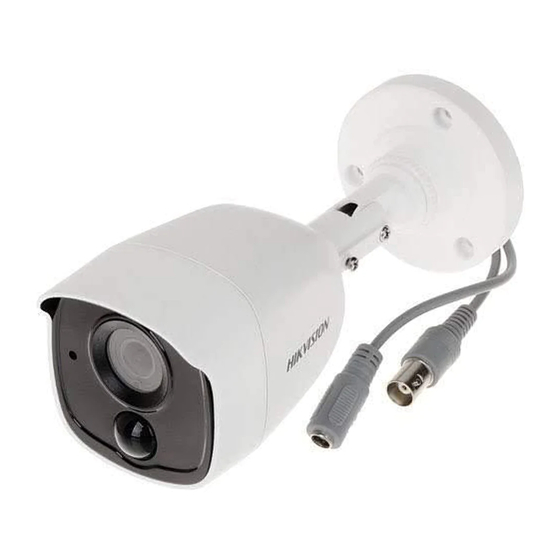
PIR Series Bullet Camera
User Manual
Thank you for purchasing our product. If there are any
questions, or requests, do not hesitate to contact the
dealer.
This manual applies to the models below:
Type I Camera
Type II Camera
This manual may contain several technical incorrect
places or printing errors, and the content is subject to
change without notice. The updates will be added to
the new version of this manual. We will readily improve
or update the products or procedures described in the
manual.
with EXT Alarm out
Type
TURBO HD
User Manual
Model
DS-2CE11D0T-PIRLO
DS-2CE11D8T-PIRLO
DS-2CE11H0T-PIRLO
DS-2CE11D0T-PIRLPO
DS-2CE11H0T-PIRLPO
DS-2CE12D0T-PIRLO
DS-2CE12D8T-PIRLO
DS-2CE12H0T-PIRLO
01000020200821
Advertisement
Table of Contents

Subscribe to Our Youtube Channel
Related Manuals for HIKVISION DS-2CE11D0T-PIRLO


Summary of Contents for HIKVISION DS-2CE11D0T-PIRLO
- Page 1 User Manual Thank you for purchasing our product. If there are any questions, or requests, do not hesitate to contact the dealer. This manual applies to the models below: Type Model DS-2CE11D0T-PIRLO DS-2CE11D8T-PIRLO Type I Camera DS-2CE11H0T-PIRLO DS-2CE11D0T-PIRLPO DS-2CE11H0T-PIRLPO DS-2CE12D0T-PIRLO...
-
Page 2: Regulatory Information
Regulatory Information FCC Information Please take attention that changes or modification not expressly approved by the party responsible for compliance could void the user’s authority to operate the equipment. FCC compliance: This equipment has been tested and found to comply with the limits for a Class A digital device, pursuant to part 15 of the FCC Rules. - Page 3 Safety Instruction These instructions are intended to ensure that user can use the product correctly to avoid danger or property loss. The precaution measure is divided into “Warnings” and “Cautions”. Warnings: Serious injury or death may occur if any of the warnings are neglected.
-
Page 4: Installation
Keep the camera away from liquid while in use for non-water-proof device. While in delivery, the camera shall be packed in its original packing, or packing of the same texture. Mark Description Table 0-1 Mark Description Mark Description DC Voltage 1 Introduction 1.1 Product Features... - Page 5 Make sure the wall is strong enough to withstand three times the weight of the camera, and the mount. If the wall is cement, insert expansion bolts before installing the camera. If the wall is wooden, use self-tapping screws to secure the camera. If the product does not function properly, contact ...
- Page 6 Pan Position [0° to 360°] P Screw Tilt Position [0° to 180°] T Screw Rotation Position R Screw [0° to 360°] Figure 2-3 3-axis Adjustment 1). Loosen the P screw to adjust the pan position [0° to 360°]. Tighten the screw after completing the adjustment.
- Page 7 Figure 2-6 Secure the Junction Box to the Wall/Ceiling 7. Route the cables through the bottom cable hole, or the side cable hole of the junction box. 8. Combine the junction box cover with its body. Figure 2-7 Combine the Junction Box Cover back to its Body 9.
-
Page 8: Ceiling/Wall Mounting With Junction Box
Figure 2-9 Install the Camera to the Ceiling Note: The supplied screw package contains self-tapping screws, and expansion bolts. For cement wall/ceiling, expansion bolts are required to fix the camera. For wooden wall/ceiling, self-tapping screws are required. 5. Connect the corresponding power cord, and video cable. -
Page 9: Menu Description
3. Take apart the junction box, and align the screw holes of the bullet camera with those on the Junction box’s cover. 4. Install the camera on the junction box’s cover with supplied screws. Figure 2-12 Install the camera on the Junction Box 5. -
Page 10: Video Format
VIDEO FORMAT EXPOSURE MODE EXPOSURE SLOW SHUTTER BACK EXIT SAVE & EXIT MODE IR LIGHT DAY/NIGHT Smart IR LEVEL D->N THRESHOLD N->D THRESHOLD BACK EXIT SAVE & EXIT IMAGE MODE WHITE BALANCE BRIGHTNESS CONTRAST VIDEO SHARPNESS SETTINGS SATURATION 3 DNR MAIN MENU MIRROR BACK... -
Page 11: Slow Shutter
GLOBAL GLOBAL refers to the normal exposure mode which adjusts lighting distribution, variations, and non-standard processing. BLC (Backlight Compensation) BLC (Backlight Compensation) compensates light to the object in the front to make it clear, but this may cause the over-exposure of the background where the light is strong. -
Page 12: Video Settings
Figure 3-3 DAY NIGHT IR LIGHT You can turn on/off the infrared to meet the requirements of different circumstances. SMART IR The Smart IR function is used to adjust the light to its most suitable intensity, and prevent the image from over exposure. - Page 13 WHITE BALANCE White balance, the white rendition function of the camera, is to adjust the color temperature according to the environment. It can remove unrealistic color casts in the image. You can set WHITE BALANCE mode as AUTO, or MANUAL. AUTO ...
-
Page 14: Motion Det
Figure 3-6 FUNCTIONS SOLID Select the ALARM MODE as SOLID. In this way, the white light source turns on, when the PIR module received the alarm signal. FLASHING Select the ALARM MODE as FLASHING. In this way, the white light source flashes when the PIR module received the alarm signal.
Need help?
Do you have a question about the DS-2CE11D0T-PIRLO and is the answer not in the manual?
Questions and answers