Table of Contents
Advertisement
Quick Links
Advertisement
Table of Contents

Related Manuals for THORLABS PFR6090-8


Summary of Contents for THORLABS PFR6090-8
- Page 1 Small Table Support System and Accessories User Guide...
-
Page 2: Table Of Contents
Chapter 4 Considerations For Ergonomic Layout .................... 9 4.1 Ergonomic Guidelines ............................9 Chapter 5 Fitting Casters ..........................11 5.1 Introduction ..............................11 5.2 Procedure ................................ 11 5.2.1 Component Parts ................................11 5.2.2 Fitting the Caster Assemblies ............................. 11 Chapter 6 Thorlabs Worldwide Contacts ......................12... -
Page 3: Chapter 1 Safety
Chapter 1 Safety 1.1 Safety Information For the continuing safety of the operators of this equipment, and the protection of the equipment itself, the operator should take note of the Warnings, Cautions and Notes throughout this handbook and, where visible, on the product itself. The following safety symbols may be used throughout the handbook and on the equipment itself. -
Page 4: Chapter 2 Getting Started
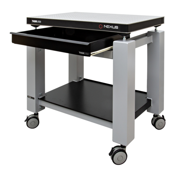
Chapter 2 Getting Started 2.1 General Description The basic workstation includes a frame consisting of four legs connected with tie bars. A breadboard or table top is supported on vibration isolation mounts and provides a stable platform on which to populate system components. Fig. -
Page 5: Chapter 3 Basic Installation
Chapter 3 Basic Installation 3.1 Installing the Frame 1) Remove all packaging. 2) Install the frame in the location in which it is to be used. 3) Adjust the feet until the castors (if fitted) are clear of the ground and the frame is level – see Fig. 3.1. Use a suitable levelling device as necessary. -
Page 6: Installing The Anti-Vibration Mounts And Breadboard
Chapter 3 3.2 Installing the Anti-vibration Mounts and Breadboard 3.2.1 Rigid Mounts 1) Ensure the frame is correctly sited and level – see Section 3.1. Warning During item (2): Breadboards should be manipulated only using appropriate lifting equipment. Breadboards should be lifted only in an unpopulated condition. The space between the edge of the breadboard and the frame is very small. -
Page 7: Passive Mounts
PFR, PFP and PFH Series Breadboard Support System 3.2.2 Passive Mounts Equipment Required: Levelling device (e.g., bubble level) Foot pump (automobile tire type) Parts supplied: Valve cap (qty 4) 1) Ensure the frame is level – see Section 3.1. 2) If fitted, remove the valve caps from each mount – see Fig. 3.3. Fig. - Page 8 Chapter 3 4) Connect the foot pump to the mount on one of the legs and inflate to about 40 p.s.i. – see Fig. 3.4. 5) Inflate the leg diagonally opposite to 40 p.s.i. 6) Repeat steps 4) and 5) for the two remaining legs. 7) Populate the breadboard.
-
Page 9: Chapter 4 Considerations For Ergonomic Layout
PFR, PFP and PFH Series Breadboard Support System Chapter 4 Considerations For Ergonomic Layout Note The workstation and its accessories have been designed to provide maximum adaptability, thereby ensuring the most ergonomically favorable work environment for the operator. When setting up the final layout of the workstation, consideration should be given to the position of the operator, the positioning of the various pieces of equipment in relation to the operator, and the duration of use for each unit. - Page 10 Chapter 4 Once the user is seated, their seating height and footrest (if used) should be adjusted so the interface with the workstation is comfortable – See Fig. 4.1 for guidance on preferred workspaces. Note For simplicity, only one body size is shown and adaptations for other body sizes will be necessary. It is advisable to leave legroom, which is free from obstructions/ bump hazards, under the desk.
-
Page 11: Chapter 5 Fitting Casters
PFR, PFP and PFH Series Breadboard Support System Chapter 5 Fitting Casters 5.1 Introduction If specified at the time of ordering, the system is supplied with casters already fitted. This section is applicable only if casters are ordered as an optional accessory at a later date. 5.2 Procedure 5.2.1 Component Parts Bolt (qty 4) -
Page 12: Chapter 6 Thorlabs Worldwide Contacts
Chapter 6 Thorlabs Worldwide Contacts For technical support or sales inquiries, please visit us at www.thorlabs.com/contact for our most up-to- date contact information. USA, Canada, and South America UK and Ireland Thorlabs, Inc. Thorlabs Ltd. sales@thorlabs.com sales.uk@thorlabs.com techsupport@thorlabs.com techsupport.uk@thorlabs.com Europe...
Need help?
Do you have a question about the PFR6090-8 and is the answer not in the manual?
Questions and answers