
Related Manuals for THORLABS Kinesis PFM450E


Summary of Contents for THORLABS Kinesis PFM450E
- Page 1 PFM450E Piezo Focus Mount and Controller Kinesis User Guide Original Instructions HA0358T...
-
Page 2: Table Of Contents
PFM450E Piezo Focus Mount and Controller Contents Chaper 1 Overview ..................... 1 1.1 Introduction ..................1 1.2 Software Overview ................3 1.2.1 Introduction ..................... 3 1.2.2 Kinesis Server ..................3 1.2.3 Software Upgrades ................. 4 Chaper 2 Safety ......................5 2.1 Safety Information ................ - Page 3 Appendix A Preventive Maintenance ............45 Appendix B Specifications and Associated Parts ........46 Appendix C Piezo Operation - Background ..........49 Appendix D Regulatory ................52 Appendix E Thorlabs Worldwide Contacts ..........55 Page 0 Rev E Mar 2022...
-
Page 4: Chaper 1 Overview
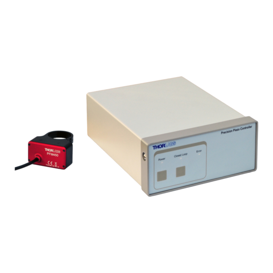
Chapter 1 Overview 1.1 Introduction Thorlabs’ PFM450E Piezo-Driven Focus Mount System provides 600 µm of travel in open loop and 450 µm in closed loop and is designed specifically for visualizing specimens or samples in applications such as confocal microscopy and 3D imaging. - Page 5 Chapter 1 Overview The piezo controller is supplied with a full suite of software support tools. An intuitive graphical instrument panel allows immediate control and visualization of the operation of the piezo controller, and any other controllers that are installed in the system. See Section 1.2.
-
Page 6: Software Overview
PFM450E Piezo Focus Mount and Controller 1.2 Software Overview 1.2.1 Introduction The PPC001 piezo controller features USB connectivity (allowing multiple units to be used together on a single PC), fully featured Graphical User Interface (GUI) panels, and extensive software function libraries for custom application development. The Kinesis software suite provides a flexible and powerful PC based control system both for users of the equipment, and software programmers aiming to automate its operation. -
Page 7: Software Upgrades
This is available either by pressing the F1 key when running the Kinesis server, or via the Start menu, Start\Programs\Thorlabs\Kinesis\Kinesis Help. 1.2.3 Software Upgrades Thorlabs operate a policy of continuous product development and may issue software upgrades as necessary. Page 4... -
Page 8: Chaper 2 Safety
To minimize the possibility of this happening it is strongly recommended that any such modes that result in prolonged unresponsiveness be disabled before the software is run. Please consult your system administrator or contact Thorlabs technical support for more details. Page 5... -
Page 9: Chaper 3 Installation
Chapter 3 Installation Chapter 3 Installation 3.1 Unpacking Caution Once removed from its packaging, the stage can be easily damaged by mishandling. The unit should only be handled by its base, not by any attachments to the moving part. The equipment contains no user servicable parts. Do not remove any screws securing the covers or attempt any repairs or adjustments as this will affect the calibration and invalidate the warranty. -
Page 10: Mounting
PFM450E Piezo Focus Mount and Controller 3.2 Mounting 3.2.1 General Caution The controller and objective mount are calibrated at the factory and are sold as a matched pair. The matched pair can be identified by the serial number label that appears on both units. Unsatisfactory performance is likely to result if the objective mount is driven by a different controller, or if the controller is used to drive other objective mounts. - Page 11 Chapter 3 Installation Ensure mounting flange sits flush with microscope Ensure mounting flange housing sits flush with piezo mount body Groove for use with flat spanner (supplied) Fixed world Moving world Clamping bolts (Direction of positive motion) Fig. 3.2 Fitting the Focus Mount Caution Proper alignment and positioning is crucial to correct functioning of the piezo mount.
-
Page 12: Fitting/Changing The Objective
PFM450E Piezo Focus Mount and Controller 3.4 Fitting/Changing the Objective Caution Fit the objective to the adapter ring before the adapter ring and objective are fitted to the piezo mount. Fitting or removing the objective whilst the adapter ring is fitted to the piezo mopunt can exert excessive torsional force and damge the internal flexures. -
Page 13: Angular Rotation
Chapter 3 Installation Caution Due to its inherent capacitance, movement or vibration of the cable may affect the stability of the stage. Where possible, arrange the cable in such a way to minimize movement and vibration while the stage is in operation. A range of objective adapters are available separately as detailed below. -
Page 14: Installing The Controller
PFM450E Piezo Focus Mount and Controller 3.5 Installing the Controller 3.5.1 Siting The unit is designed to be mounted free standing on a shelf, benchtop or similar surface. Caution Ensure that proper airflow is maintained to the sides of the unit. 3.5.2 Environmental Conditions Warning Operation outside the following environmental limits may adversely affect... -
Page 15: Installing The Software
3.6 Installing the Software Caution Thorlabs often releases updated firmware for bug fixes and support for new features. We recommend all users to download the latest version of Kinesis software and use the included firmware update utility. Failure to do this could result in stages not being recognized by the latest controllers. -
Page 16: Connecting The Hardware
3 metres can be achieved by using a powered USB hub). 5) Windows should detect the new hardware. Wait while Windows installs the drivers for the new hardware - see the Getting Started guide for more information 6) Run the Kinesis software - Start/Programs/Thorlabs/Kinesis/Kinesis. Page 13 ETN018233-D03... -
Page 17: Powering Down The Controller
Chapter 3 Installation 7) Check that the Graphical User Interface (GUI) panel appears and is active. Fig. 3.5 GUI panel showing jog and ident buttons 8) Click the ‘Identify’ button. The POWER LED on the front panel of the controller flashes. -
Page 18: Rear Panel Connections
PFM450E Piezo Focus Mount and Controller 3.7.4 Rear Panel Connections 150V Fig. 3.6 Rear panel connections STAGE - Provides the drive signal to the piezo actuator, -30 V to 150 V, 0 to 150 mA. Note Ensure that the mating faces of the connectors are properly aligned. Misalignment can cause connection problems. - Page 19 Chapter 3 Installation Caution Before the input can be used, the Drive Input Source must be set to a BNC (+SW) option in the Settings panel (see Section 5.2.2.) or in software by calling the appropriate message. When driving the piezo mount from an external source, the external signal is added to the software input (GUI panel or SetVoltOP software method) and, if connected and selected, the Joystick.
-
Page 20: Front Panel Controls And Indicators
PFM450E Piezo Focus Mount and Controller 3.8 Front Panel Controls and Indicators Precision Piezo Controller Power Closed Loop Error Fig. 3.7 Front panel controls and indicators Power Button and LED – Applies and removes power to the controller. Power is applied when the LED is lit. -
Page 21: Controller Schematic Diagram
Chapter 3 Installation 3.9 Controller Schematic Diagram The PPC001 controller and PFM450 focus mount is a closed-loop position control system with a digital PID controller and dual notch filters. The PFM450 actuator contains a capacitive position sensor for accurate position measurement. The sensor is driven from a sine wave generator, the AC output signal of the actuator is demodulated and sampled by a precision 18 bit A/D converter. - Page 22 PFM450E Piezo Focus Mount and Controller Fig. 3.9 System Schematic - Part 2 Page 19 ETN018233-D03...
-
Page 23: Chaper 4 Pc Operation - Tutorial
2) Switch ON the controller. 3) Power up the hardware, and wait until the PPC001 has finished booting up, then run the software - Start/All Programs/Thorlabs/Kinesis/Kinesis. The software registers automatically the units connected on the USB bus and displays the associated GUI panels as shown in Fig. - Page 24 Caution The PFM450 Focus Mount contains a capacitive feedback sensor and can be driven only by the Thorlabs PPC001 150V Piezo Controller. The controller and objective mount are calibrated at the factory and are sold as a matched pair. The matched pair can be identified by the serial number label that appears on both units.
-
Page 25: Introduction To Open And Closed Loop Operation
Chapter 4 PC Operation - Tutorial 4.3 Introduction to Open and Closed Loop Operation The PPC001 Precision Piezo Controller has two distinct modes of operation: open and closed loop mode. In open loop mode, the output voltage is controlled directly, using a joystick, the external BNC input, the GUI or a combination of these. -
Page 26: Limitations On The Displayed Position Values
PFM450E Piezo Focus Mount and Controller The following section describes details a typical tuning procedure 1) Measure and record the objective mass. 2) Fit the PFM450 to the microscope - see Section 3.3. 3) Fit the objective to the microscope - see Section 3.4. 4) Switch on the controller and leave to warm up for at least 30 minutes. -
Page 27: Moving The Piezo Mount
Chapter 4 PC Operation - Tutorial 4.6 Moving the Piezo Mount The piezo mount can be manually positioned in two ways: by entering a voltage/ position, or by clicking the ‘Jog’ buttons. 4.6.1 Setting the Zero Position Upon power up, the controller is set to 0V and open loop. Typical operation involves moving to a position visually in open loop and then switching to closed loop, which maintains the stage position to that achieved at the moment of switch over. -
Page 28: Jogging The Piezos
PFM450E Piezo Focus Mount and Controller 5) Click the arrow to save the change. Notice that the position display counts up to 10.00 to indicate a move to a position 10µm from the Zero datum. 4.6.3 Jogging the Piezos When the Step buttons are pressed, the piezo moves by the step size specified in the Jog Step Size parameter. -
Page 29: Using The Controller As A Piezo Amplifier
Chapter 4 PC Operation - Tutorial 4.7 Using the Controller as a Piezo Amplifier Certain applications may require the piezo to be driven by a voltage generated from an external source (e.g. 0 to 10V output). To achieve this, the controller must handle the amplification from 10V to 75V. -
Page 30: Thermal Shutdown
PFM450E Piezo Focus Mount and Controller 4.8 Thermal Shutdown In order to protect the piezo driver card from overheating due to abnormal load conditions, the electronics contains thermal protection circuitry. When the protection is activated, the HV output its shut down, limiting the maximum output current to a few milliamps, and the ‘Error’... -
Page 31: Load Response
Chapter 4 PC Operation - Tutorial 4.10 Load Response The response of the PPC001 to varying load and frequencies is shown below. Fig. 4.4 Response of PPC001 to Varying Loads and Frequencies Page 28 Rev E Mar 2022... -
Page 32: Chaper 5 Software Reference
PFM450E Piezo Focus Mount and Controller Chapter 5 Software Reference 5.1 GUI Panel The following screen shot shows the graphical user interface (GUI) (one panel per card fitted) displayed when accessing the controller using the software. Fig. 5.1 PPC001 Piezo Driver Software GUI Note The serial number of the PPC001 unit associated with the GUI panel, is displayed in the top right hand corner. -
Page 33: Settings Panel
Chapter 5 Software Reference Settings - Displays the 'Settings' panel, which allows the operating parameters to be entered for the motor drive - see Section 5.2. Open Loop and Closed Loop LEDs - When Open Loop or Closed Loop mode is selected, the corresponding LED is lit. Identify - when this button is pressed, the main display on the front panel of the associated hardware unit will flash for a short period. -
Page 34: Advanced Tab
PFM450E Piezo Focus Mount and Controller 5.2.2 Advanced tab. Fig. 5.2 Piezo Settings panel - Advanced tab IO Settings Control Mode - determines the input source(s) which control the output from the HV amplifier circuit (i.e. the drive to the piezo actuators). Software Only - the unit responds only to software inputs and the piezo drive output is that set using the Software message calls (or the GUI panel ). - Page 35 Chapter 5 Software Reference means of monitoring the position stability and fine tuning the settings. This parameter sets the type of signal being monitored - see also Section 3.9. If High Voltage Output is selected, the signal driving the EXT OUT (Monitor) BNC is a scaled down version of the piezo output voltage, with 150 V piezo voltage corresponding to 10V.
-
Page 36: Filters Tab
PFM450E Piezo Focus Mount and Controller 5.2.3 Filters tab. Fig. 5.3 Piezo Settings panel - Loop Tuning tab When operating in Closed Loop mode, the proportional, integral and differential (PID) constants can be used to fine tune the behaviour of the feedback loop to changes in the output voltage or position. - Page 37 Chapter 5 Software Reference Fig. 5.4 P and I parameter values v load It is also possible to tune the PID loop using slider controls. To display these controls click the Tune button. These slider controls adjust the settings for the PID parameters, and any changes are applied immediately.
- Page 38 PFM450E Piezo Focus Mount and Controller Once satisfactory performance is obtained, click OK to save the settings. Warning High amplitude oscillation due to inappropriate PID/Notch filter parameter settings can cause damage to the piezo mount. If such oscillation is apparent, switch immediately to open loop or disable the mount.
- Page 39 Chapter 5 Software Reference adjustable electronic anti-resonance that can be used to counteract the natural resonance of the mechanical system. Fig. 5.5 Notch filter settings v load Page 36 Rev E Mar 2022...
- Page 40 PFM450E Piezo Focus Mount and Controller As the resonance frequency of actuators varies with load in addition to the minor variations from product to product, the notch filter is tuneable so that its characteristics can be adjusted to match those of the actuator. In addition to its centre frequency, the bandwidth of the notch (or the equivalent quality factor, often referred to as the Q- factor) can also be adjusted.
- Page 41 Chapter 5 Software Reference bandwidth, and defines how wide the notch is, a higher Q factor defining a narrower ("higher quality") notch. Either one or two notch filters can be used, and the settings appear when the ‘Use Notch Filter’ boxes are checked. The center frequency is specified in Hz in the range 20 to 500.
-
Page 42: Appendix A Rear Panel Connector Pinout Detail
† Power supply for the piezo actuator feedback circuit. It must not be used to drive any other circuits or devices. * This signal is applicable only to Thorlabs actuators. It enables the system to identify the piezo extension associated with the actuator. - Page 43 Appendix A Rear Panel Connector Pinout Detail A.2 Rear Panel USER Connector A.2.1 Pin Identification This female 15-pin D-Type connector exposes a number of internal electrical signals. For convenience, a number of logic inputs and outputs are included, thereby eliminating the need for extra PC based IO hardware. Using the software, these user programmable logic lines can be deployed in applications requiring control of external devices such a relays, light sources and other auxilliary equipment.
- Page 44 PFM450E Piezo Focus Mount and Controller A.2.2 Digital Outputs All digital outputs are of the open-collector type, with a 330 Ohm series resistor. When the output is set to a logic zero (which is also the default state), it behaves as open circuit.
- Page 45 Appendix A Rear Panel Connector Pinout Detail A.2.3 Digital Inputs The digital inputs used in the controller are of the standard CMOS logic gate type with TTL compatible input levels and a built-in pull-up resistor (10 kOhm to +5V). They can be connected directly to mechanical switches, open-collector type outputs or most type of logic outputs.
- Page 46 PFM450E Piezo Focus Mount and Controller A.2.5 Trigger Input The Trigger inputs are ekectrically identical to the digital inputs (i.e. a standard CMOS logic gate type with TTL compatible input levels and a built-in pull-up resistor, 10 kOhm to +5V). They can be connected directly to mechanical switches, open- collector type outputs or most type of logic outputs.
- Page 47 Appendix A Rear Panel Connector Pinout Detail A.3 Rear Panel RS232 Connector The RS232 terminal is a Male 9-Pin D-type connector exposes internal electrical signals for use with serial communications. This allows control of the device using the low level protocol in software environments that bypass Kinesis server. A 9-way female- to-female crossover (zero modem) cable is required for connecting to a host PC.
-
Page 48: Appendix A Preventive Maintenance
The equipment contains no user servicable parts. There is a risk of electrical shock if the equipment is operated with the covers removed. Only personnel authorized by Thorlabs Ltd and trained in the maintenance of this equipment should remove its covers or attempt any repairs or adjustments. Maintenance is limited to safety testing and cleaning as described in the following sections. -
Page 49: Appendix B Specifications And Associated Parts
Appendix C Specifications and Associated Parts Appendix C Specifications and Associated Parts C.1 Objective Mount Specifications Parameter Value Drive Voltage -30 V to 150 V Open Loop Travel Range 600 µm ±10% Closed Loop Travel Range 450 µm Feedback Transducer Type Capacitive Open Loop Resolution 1 nm... - Page 50 PFM450E Piezo Focus Mount and Controller C.2 Controller Specifications Parameter Value Piezoelectric Output (Mixed Signal Combination D-Sub Connector) Voltage Output -30 V to 150 V DC Output Current 150 mA Voltage Stability 100ppm over 24 hours (after 30 mins warm up time) Noise <0.5 mV RMS (Bandwidth 20 Hz to 100 kHz)* Typical Piezo Capacitance...
- Page 51 Version 2.0 Full Speed Compatible RS-232 3-wire Interface (RX, TX, GND) via 9-way D-type male connecvtor Joystick Compatible with Thorlabs MZF001 Joystick Closed Loop Algorithm Digital PID with Dual Tuneable Notch Filter Processor DSP 32-bit Floating Point, 160 MHz (ARM Cortex M4F) Servo Update Interval 50 µs...
-
Page 52: Appendix C Piezo Operation - Background
– see Fig. D.1. In this way, the distance from positive to negative electrodes is very small. A large field gradient can therefore be obtained with a modest drive voltage (75 V or 150 V in the case of Thorlabs actuators). expansion piezoelectric... - Page 53 Some Thorlabs nanopositioning actuators have position sensing, others do not. The Piezoelectric control module allows both types to be controlled.
- Page 54 PFM450E Piezo Focus Mount and Controller moving open loop control part demand actuator moving closed loop control part demand a + b/s actuator sensor Fig. D.3 Open loop and closed loop control The result of using closed-loop control is a linear relationship between demand (voltage) and measured position –...
-
Page 55: Appendix D Regulatory
Appendix E Regulatory Appendix E Regulatory E.1 Declarations Of Conformity E.1.1 For Customers in Europe See Section E.2. E.1.2 For Customers In The USA This equipment has been tested and found to comply with the limits for a Class A digital device, persuant to part 15 of the FCC rules. - Page 56 PFM450E Piezo Focus Mount and Controller E.2 CE Certificate Page 53 ETN018233-D03...
- Page 57 Appendix E Regulatory Page 54 Rev E Mar 2022...
-
Page 58: Appendix E Thorlabs Worldwide Contacts
Waste treatment is your own responsibility. "End of life" units must be returned to Thorlabs or handed to a company specializing in waste recovery. Do not dispose of the unit in a litter bin or at a public waste disposal site. - Page 59 www.thorlabs.com...
Need help?
Do you have a question about the Kinesis PFM450E and is the answer not in the manual?
Questions and answers