Table of Contents
Advertisement
Quick Links
Advertisement
Table of Contents

Related Manuals for THORLABS PDX1


Summary of Contents for THORLABS PDX1
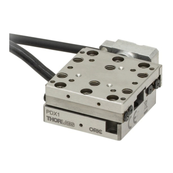
- Page 1 PDX1(/M) Piezo Inertia Drive Stage with Optical Encoder User Guide...
-
Page 3: Table Of Contents
PDX1 Piezo Inertia Drive Stage with Optical Encoder Table of Contents Chapter 1 Warning Symbol Definitions .................... 1 Chapter 2 Safety ............................ 2 2.1. Safety Information ......................2 2.2. General Warnings ......................2 2.3. General Cautions ......................3 2.4. General Notes ........................3 ... -
Page 5: Chapter 1 Warning Symbol Definitions
PDX1 Piezo Inertia Drive Stage with Optical Encoder Chapter 1: Warning Symbol Definitions Chapter 1 Warning Symbol Definitions Below is a list of warning symbols you may encounter in this manual or on your device. Symbol Description Direct Current Alternating Current... -
Page 6: Chapter 2 Safety
PDX1 Piezo Inertia Drive Stage with Optical Encoder Chapter 2: Safety Chapter 2 Safety 2.1. Safety Information For the continuing safety of the operators of this equipment, and the protection of the equipment itself, the operator should take note of the Warnings, Cautions, and Notes throughout this manual and, where visible, on the product itself. -
Page 7: General Cautions
PDX1 Piezo Inertia Drive Stage with Optical Encoder Chapter 2: Safety 2.3. General Cautions CAUTION Dust and debris can reduce the lifetime of the stage. If left running unattended for extended periods of time, the application should be covered where possible. -
Page 8: Chapter 3 Overview
3.1. Introduction The PDX1(/M) stage features a piezo inertia motor that uses friction and inertia to translate the platform in discrete cycles. Each cycle consists of a relatively slow piezo expansion step accompanied by a rapid piezo contraction step. During the expansion step, the moving platform moves in the same direction as the piezo element due to friction, while the rapid piezo contraction causes the moving platform to slip and remain immobile due to inertia. -
Page 9: Pin Diagram
Unpack the stage with care, checking the contents for signs of damage. If there is any sign of damage or missing parts, contact Thorlabs immediately. Please do not touch the optical scale when unpacking the stage. If necessary, clean the scale using N-heptane or isopropyl alcohol on a dust-free cloth. -
Page 10: Accessories
3.5. Accessories The PD1B(/M) adapter provides a flat surface for mounting the PDX1(/M) stage. The PD1T(/M) adapter plate features a central 8-32 (M4) tapped hole. Both imperial and metric versions have four 4-40 tapped holes on 16 mm spacings for 16 mm cage systems. -
Page 11: Chapter 4 Installation
Mount the PDX1(/M) stage on an even surface. The recommended flatness of the surface is ≤5 μm. For applications with large temperature variation, only mount the PDX1(/M) stage on a surface that has the same or similar thermal expansion properties as the stage. - Page 12 PDX1 Piezo Inertia Drive Stage with Optical Encoder Chapter 4: Installation Thorlabs offers a standard mounting plate, PD1B(/M), to provide a flat surface for mounting the stage and a 1.00" (25.0 mm) long #8 (M4) counterbored slot for mounting the plate to an optical table or breadboard.
-
Page 13: Attaching Shipping Plate
A thin shipping plate is included with each stage to provide a convenient means of locking the stage's moving world (carriage plate) using three M1.4 cap screws (also included). 1. Align the shipping plate included in the package with the mounting holes in the side of the PDX1(/M) stage, as shown below. -
Page 14: Setting Up An Xy Or Xyz Stage Configuration
PDX1 Piezo Inertia Drive Stage with Optical Encoder Chapter 4: Installation Shipping Plate Figure 7 Shipping Plate Mount on Multi-Axis System 4.1.3. Setting Up an XY or XYZ Stage Configuration CAUTION In a multi-axis system, upper stage(s) and any mounting adapters must also be moved and should be considered as part of the load. - Page 15 PDX1 Piezo Inertia Drive Stage with Optical Encoder Chapter 4: Installation 2-56 (M2) Cap Screw, 4 mm Long Ø2 mm Dowel Pin, 3 mm Long Figure 8 Setting Up an XY Axis Configuration To set up an XYZ-axis system, first build the XY-axis system as above and then attach the PD1Z(/M) Z-bracket adapter plate to mount another PDX1(/M) stage vertically.
- Page 16 PDX1 Piezo Inertia Drive Stage with Optical Encoder Chapter 4: Installation 2-56 (M2) Cap Screw, 4 mm Long Ø2 mm Dowel Pin, 3 mm Long Figure 9 Setting Up an XYZ Axis Configuration 5. Insert another two Ø2 mm, 3 mm long dowel pins into the vertical plane’s two holes in diagonal corners.
-
Page 17: Mounting Components To The Stage
PDX1 Piezo Inertia Drive Stage with Optical Encoder Chapter 4: Installation 4.1.4. Mounting Components to the Stage CAUTION Do not exceed the load capacity specified in Chapter 6. The load’s center of mass should be over the platform. Do not use screws and dowel pins that protrude past the maximum hole depth. - Page 18 Thorlabs offers a thin mounting adapter plate, PD1T(/M), to provide a convenient means of attaching a load to the PDX1(/M) series stages by a central 8-32 (M4) tapped hole and other 4-40 (M2 & M3) tapped holes. Both imperial and metric versions have four 4-40 tapped holes spaced for 16 mm cage systems. The following is an example to show how to mount a PD1T(/M) plate to a PDX1(/M) stage.
- Page 19 PDX1 Piezo Inertia Drive Stage with Optical Encoder Chapter 4: Installation Thorlabs also offers a thick mounting adapter plate, PD1U(/M), to provide a convenient means of attaching a load to the PDX1(/M) stages using five #8 (M4) counterbores, as shown below: 1.
-
Page 20: Electrical Connections
The stage is shipped with a 1.5 m (5.0 ft) cable that is terminated in a 15-pin D-SUB female connector. Connect the PDX1(/M) stage to the 15-pin D-SUB male terminal on the front panel of the PDXC controller. For pin-out details, refer to the PDXC controller manual. -
Page 21: Chapter 5 Operation
Confirm the configuration of the PDXC controller prior to use. Since the controller can drive both PD1(/M) and PDX1(/M) stages, the wrong configuration will not drive the stage properly and there is a risk of damage to the stage and/or the controller. -
Page 22: Maintenance
Periodic maintenance helps to ensure the optimum stepping performance during its life span. NOTE The PDX1(/M) stage is assembled with rust preventative oil. Do not wipe the stage with organic solvents. When necessary, clean the surfaces of the stage with a dry, dust-free cloth. -
Page 23: Chapter 6 Specifications
PDX1 Piezo Inertia Drive Stage with Optical Encoder Chapter 6: Specifications Chapter 6 Specifications Item # PDX1(/M) Travel Range 20 mm (0.78") Optical Encoder Resolution 10 nm Minimal Incremental Motion 20 nm PDXC Only Step Size 0.01 to 10.00 mm PDXC with Software Step Size 0.00001 to 10.00 mm... -
Page 24: Chapter 7 Frequently Asked Questions
50% or more over time. What driver can I use? The PDX1(/M) stage must be driven by a Thorlabs PDXC controller with a firmware revision of 1.2.4 or higher. What is the maximum length of cable? The stages are shipped with 1.5 m (5.0 ft) of cable. -
Page 25: Chapter 8 Mechanical Drawings
PDX1 Piezo Inertia Drive Stage with Optical Encoder Chapter 8: Mechanical Drawings Chapter 8 Mechanical Drawings Figure 13 PDX1/M Metric Stage Drawing Rev A, May 26, 2021 Page 21... - Page 26 PDX1 Piezo Inertia Drive Stage with Optical Encoder Chapter 8: Mechanical Drawings Figure 14 PDX1 Imperial Stage Drawing Page 22 CTN015392-D02...
-
Page 27: Chapter 9 Regulatory
Waste Treatment is Your Own Responsibility If you do not return an “end of life” unit to Thorlabs, you must hand it to a company specialized in waste recovery. Do not dispose of the unit in a litter bin or at a public waste disposal site. -
Page 28: Chapter 10 Declarations Of Conformity
PDX1 Piezo Inertia Drive Stage with Optical Encoder Chapter 10: Declarations of Conformity Chapter 10 Declarations of Conformity Page 24 CTN015392-D02... -
Page 29: Chapter 11 Thorlabs Worldwide Contacts
PDX1 Piezo Inertia Drive Stage with Optical Encoder Chapter 11: Thorlabs Worldwide Contacts Chapter 11 Thorlabs Worldwide Contacts For technical support or sales inquiries, please visit us at www.thorlabs.com/contact for our most up-to-date contact information. USA, Canada, and South America UK and Ireland Thorlabs, Inc. - Page 30 www.thorlabs.com...
Need help?
Do you have a question about the PDX1 and is the answer not in the manual?
Questions and answers