Table of Contents
Advertisement
Quick Links
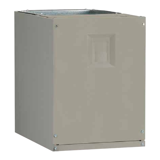
MODULAR AIR HANDLER
INSTALLATION INSTRUCTIONS
MB7VM SINGLE PHASE SERIES
MB7EM 3-PHASE SERIES
It is your responsibility to know this product better than your customer. This includes being
able to install the product according to strict safety guidelines and instructing the customer on
how to operate and maintain the equipment for the life of the product. Safety should always be
the deciding factor when installing this product and using common sense plays an important
role as well. Pay attention to all safety warnings and any other special notes highlighted in the
manual. Improper installation of the furnace or failure to follow safety warnings could result in
serious injury, death, or property damage.
These instructions are primarily intended to assist qualified individuals experienced in the proper
installation of this appliance. Some local codes require licensed installation/service personnel
for this type of equipment. Please read all instructions carefully before starting the installation.
Return these instructions to the customer's package for future reference.
DO NOT DESTROY. PLEASE READ CAREFULLY & KEEP IN A SAFE PLACE FOR FUTURE REFERENCE.
IMPORTANT
ATTENTION INSTALLERS:
Advertisement
Table of Contents

Related Manuals for Nortek MB7VM SINGLE PHASE Series


Summary of Contents for Nortek MB7VM SINGLE PHASE Series
- Page 1 MODULAR AIR HANDLER INSTALLATION INSTRUCTIONS MB7VM SINGLE PHASE SERIES MB7EM 3-PHASE SERIES IMPORTANT ATTENTION INSTALLERS: It is your responsibility to know this product better than your customer. This includes being able to install the product according to strict safety guidelines and instructing the customer on how to operate and maintain the equipment for the life of the product.
-
Page 2: Table Of Contents
TABLE OF CONTENTS IMPORTANT SAFETY INFORMATION ......3 STARTUP & ADJUSTMENTS ..........9 Before You Start the Air Handler ........9 GENERAL INFORMATION ..........3 Air Circulation Check ............10 Requirements & Codes ............ 3 Running the Blower Continuously ........ 10 About the Air Handler ............ -
Page 3: Important Safety Information
IMPORTANT SAFETY INFORMATION paper products, gasoline, kerosene, cigarette lighter fluid, dry cleaning fluids, paint thinners, or other volatile fluids. Please read all information in this manual thoroughly and become • Installation of equipment may require brazing operations. familiar with the capabilities and use of this appliance before Installer must comply with safety codes and wear appropriate attempting to service or maintain this unit. -
Page 4: Minimum Clearances
Minimum Clearances 90B), and all applicable local codes. NFPA publications are available by writing to: National Fire Protection • This appliance must be installed in accordance with clearances Association, Batterymarch Park, Quincy, ME 02269 or visit listed in Table 1. The air handler must be installed with ample clearance for easy access to the air filter, blower assembly, www.NFPA.org online. -
Page 5: Return Air Connections
Downflow Applications: Position the blower over the duct and Condensate Drainage secure together with sheet metal screws. CAUTION: Return Air Connections The return air must be delivered to the blower by duct(s) secured The air handler must be level to ensure proper to the casing, running full size and without interruption. -
Page 6: Downflow Installation
units and apply the black neoprene gasket tape to the top of the coil case (except the rear surface). Make sure there are no gaps on the front and side flanges. 2. Carefully place the modular air handler on top of the cased coil making sure not to damage the cased coil flanges. -
Page 7: Horizontal Left Installations
If suspending the air handler from the ceiling, assemble a support frame (Figure 5) using slotted iron channel and full threaded rod. Fasten the frame together with nuts, washers, and lockwashers. Secure the support frame to the rafters with lag bolts. The air handler can also be suspended using steel straps around each end of the unit. -
Page 8: Electrical Connections
ELECTRICAL CONNECTIONS unit and for proper grounding. Field supplied bushings for the power supply cables must be added to support and protect the power supply cables. WARNING: • All 208/230 Volt units are shipped from the factory wired for 240 volt operation. For 208V operation, remove the lead from the transformer terminal marked 240V and connect it to the ELECTRICAL SHOCK, FIRE OR terminal marked 208V. -
Page 9: Twinning
1. Connect the 2 wire plug of the air handler to the mating 2 blower off delay in cooling. See Figure 11 (page 19), Figure wire plug of the heater kit. 12 (page 20), & Figure 13 (page 20) for control board layout 2. -
Page 10: Air Circulation Check
ways to set up the air handler it is important to read and follow Air Circulation Check these directions carefully. Running the Blower Continuously Set the thermostat’s system mode to OFF and the thermostat’s MB7EM & MB7VM air handlers use high efficiency circulating fan mode to ON. -
Page 11: Unit Maintenance
UNIT MAINTENANCE Blower Motor & Assembly - Inspect the blower assembly and motor mounting brackets for tightness and corrosion. Correct Proper maintenance is most important to achieve the best deficiencies if necessary. The blower motor contains sealed performance from an air handler. Some of the components bearings and under normal operating conditions, no maintenance and their locations are shown in Figure 8 (page... -
Page 12: Figures & Tables
FIGURES & TABLES 3/4 TYP. “E” 12 7/8 VIEW Ø1 1/8” K.O. "A" (TYP.) 1 1/4 Ø 1 7/8 K.O. 2 7/8 1 3/4 1 1/4 3 1/4 2 5/8 1” 1 7/8 1 7/8 3 1/2 5 1/2 Ø 7/8 K.O. Ø1 1/8”... - Page 13 Outlet Heater Box Heating Element Assembly Motor Control Board Control Board Transformer Blower Wheel Blower Blower Rear Housing Door Bracket Blower Motor Motor Lower Front Mount Kit Bracket Front Joining Bracket Coil Assembly Figure 8. MB7 Component Locations...
-
Page 14: Blower Performance Data
Blower Performance Data COOLING OR HEATING AIRFLOW (CFM) SWITCH SETTINGS CABINET 0 = OFF, 1 = ON DRY COIL ESP SIZE — — — — — — — — — 1091 1007 1240 1160 1064 1376 1274 1209 1123 1057 1484 1426 1360... - Page 15 COOLING AIRFLOW HEATING AIRFLOW COOL SWITCH SETTING HEATER KIT A/B SWITCH SETTING AIRFLOW A/B SWITCH SETTING AIRFLOW 0 = OFF, 1 = ON INSTALLED 0 = OFF, 1 = ON (CFM) 0 = OFF, 1 = ON (CFM) (KW) 1000 1000 1300 MB7VM...
-
Page 16: Electrical Data & Diagrams
Electrical Data & Diagrams MINIMUM CIRCUIT AMPACITY & MAXIMUM OVERCURRENT PROTECTION VOLTAGE, CABINET MODEL CAPACITY CIRCUIT CIRCUIT CIRCUIT SINGLE CIRCUIT CIRCUIT CIRCUIT SINGLE HZ, & PHASE SIZE CIRCUIT CIRCUIT 1,200 CFM 240 VAC, 50 & 60 Hz, 1,600 CFM Single Phase 2,000 CFM MB7VM 1,200 CFM... - Page 17 CONTROL SIGNAL & MODE OPERATION TOTAL KW BOARD ACTION Stage 1 Heat on instantly 5 KW Heat blower on after 3 second delay Stage 1 Heat on instantly 10 KW Heat blower on after 3 second delay Stage 1 Heat on instantly 15 KW Heat blower on after 3 second delay W1 ONLY...
- Page 18 Thermostat Thermostat Thermostat NOTE: Jumper W1 & W2 together if not using W2 on thermostat Conditioner Handler Conditioner Conditioner Y/Y2 Y/Y2 Handler Handler Typical Air Conditioner with Typical Air Conditioner with Typical 2-Stage Air Conditioner Standard Air Handler Variable Speed Air Handler with Variable Speed Air Handler Thermostat Thermostat...
- Page 19 A/H #2 A/H #1 C R Y G W C R Y G W Thermostat Outdoor Unit See Figure 9 (page 18) Figure 10. Low Voltage Wiring For Twinning EXPANSION PORT LED 1 HEATER P1 Figure 11. Two - Stage Control Board (All Models)
- Page 20 DHUM TWIN OFF ON THERMOSTAT CONNECTION TERMINAL TO TWIN FURNACES GREEN NOT USED Figure 12. Fixed Speed Motor Control Board (MB7EM Models) STATUS LIGHTS L2-IN L2-OUT Y/Y2 L1-IN L1-OUT DEHUM FAN SPEED 2 3 4 5 6 7 8 TEST PORT COOL HEAT SENSOR...
- Page 21 Figure 14. MB7EM (460 V) Wiring Diagram...
- Page 22 WIRING DIAGRAM Air Handler with Variable Speed High Efficiency Motor Remarques 1. Le connecteur de vitesse du moteur du ventilateur peut NOTES: différer 1. The blower motor speed tap connection may not be as shown. de l’illustration. Consultez les Instructions d’installation. See the Installation Instructions.
-
Page 24: Installation Checklist
Please read all instructions carefully before starting the installation. Return these instructions to the customer’s package for future reference. Specifications & illustrations subject to change without notice or incurring obligations (08/19). 10274060 O’Fallon, MO, © Nortek Global HVAC LLC 2019. All Rights Reserved. (Replaces 10253260)
Need help?
Do you have a question about the MB7VM SINGLE PHASE Series and is the answer not in the manual?
Questions and answers