Table of Contents
Advertisement
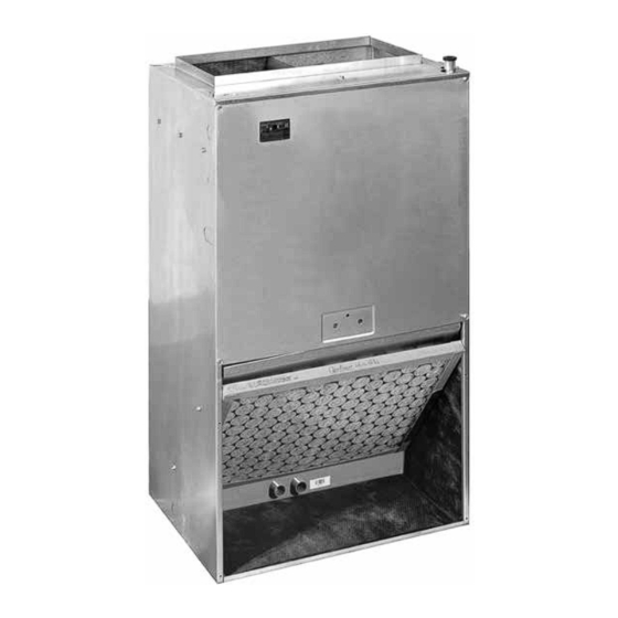
B6BW Series
INSTALLATION INSTRUCTIONS
Vertical Wall Mount Air Handler
WARNING
ELECTRICAL SHOCK, OR FIRE HAZARD
Failure to follow safety warnings exactly could
result in serious injury or property damage.
Improper servicing could result in dangerous
operation, serious injury, death or property
damage.
• Before servicing, disconnect all electrical
power to furnace.
• When servicing controls, label all wires
prior to disconnecting. Reconnect wires
correctly.
• Verify proper operation after servicing.
DO NOT DESTROY. PLEASE READ CAREFULLY & KEEP IN A SAFE PLACE FOR FUTURE REFERENCE.
NE PAS DÉTRUIRE. VEUILLEZ LIRE ATTENTIVEMENT ET CONSERVER EN UN LIEU SÛR POUR RÉFÉRENCE ULTÉRIEURE.
AVERTISSEMENT
RISQUE D'INCENDIE OU D'EXPLOSION
Le non-respect des avertissements de sécurité pourrait
entraîner un fonctionnement dangereux de l'appareil, des
blessures graves, la mort ou des dommages matériels.
Un entretein incorrect pourrait entraîner un fonctionnement
dangereux de l'appareil, des blessures graves, la mort
ou des dommages matériels.
• Couper toute alimentation électrique au générateur
d'air chaud avant de prodéder aux travaux d'entretein.
• Au moment de l'entretien des commandes, étiquetez
tous les fils avant de les débrancher. S'assurer de les
raccorder correctement.
• S'assurer que l'appareil fonctionne adéquatement
aprés l'entretien.
Advertisement
Table of Contents

Related Manuals for Nortek B6BW Series


Summary of Contents for Nortek B6BW Series
- Page 1 B6BW Series INSTALLATION INSTRUCTIONS Vertical Wall Mount Air Handler WARNING AVERTISSEMENT RISQUE D’INCENDIE OU D’EXPLOSION ELECTRICAL SHOCK, OR FIRE HAZARD Le non-respect des avertissements de sécurité pourrait Failure to follow safety warnings exactly could entraîner un fonctionnement dangereux de l’appareil, des result in serious injury or property damage.
-
Page 2: Table Of Contents
TABLE OF CONTENTS IMPORTANT SAFETY INFORMATION INSTALLER: Please read all instructions before servicing IMPORTANT SAFETY INFORMATION ......2 this equipment. Pay attention to all safety warnings and REQUIREMENTS & CODES ..........3 any other special notes highlighted in the manual. Safety markings are used frequently throughout this manual to GENERAL INFORMATION ..........4 designate a degree or level of seriousness and should not Before You Install this Unit .......... -
Page 3: Requirements & Codes
• Installation of equipment may require brazing WARNING: operations. Installer must comply with safety codes and wear appropriate safety equipment (safety glasses, work gloves, fire extinguisher, etc.) when NITROGEN performing brazing operations. • Install this unit only in a location and position as HEALTH specified on page... -
Page 4: General Information
GENERAL INFORMATION Locating the Air Handler • Survey the job site to determine the best location for This appliance has been tested for capacity and efficiency mounting the unit. Consideration should be given to in accordance with A.H.R.I. Standards and will provide availability of electric power, service access, many years of safe and dependable comfort, providing noise. -
Page 5: Installation In A Garage
furnace must be cleaned and/or repaired if found to • Plenums and air ducts must be installed in accordance be dirty, damaged, or malfunctioning in any way by with the Standard for the Installation of Air Conditioning a qualified HVAC technician. The air handler shall be and Ventilating Systems (NFPA No. -
Page 6: Air Handler Installation
AIR HANDLER INSTALLATION For hanging applications, these units are provided with 2-piece offset hanging bracket attached to the rear of the The B6BW Air Handler is shipped ready for vertical upflow cabinet. See Figure 1.Mounting bracket dimensions are installation and can be mounted directly on a wall or shown in Figure 4 (page 13). -
Page 7: System Depressurization
CAUTION: CAUTION: This unit uses refrigerant R-410A. DO NOT use It is recommended that a wet rag be wrapped any other refrigerant in this unit. Use of another around the suction line before applying heat. refrigerant will damage the unit. Failure to keep components cool during brazing may result in structural damage, premature •... -
Page 8: Electrical Wiring
ELECTRICAL WIRING • Both adapters should be made of PVC or similar material and contain a rubber washer. Hand tightened WARNING: the adapters to the drain pan. DO NOT use pliers or any other tools. Overtightening may crack the drain pan and cause condensate to leak. -
Page 9: Grounding
Thermostat Thermostat G R C E NOTE: Jumper between W2 & E is required when Handler no OD T-Stat is used. Handler Conditioner Heat Pump Typical Air Conditioner with Typical Heat Pump with Standard Air Handler Standard Air Handler Figure 3. Typical Thermostat Connections See the unit rating plate and Table 2 (page 8) Thermostat Connections... -
Page 10: Startup & Adjustments
STARTUP & ADJUSTMENTS HEAT COOL WARNING: M1 = Low speed Off Off Off Off On On Off Off Off Off M2 = Med. Low Sp. Off Off Off On Off Off On Off Off Off NITROGEN M3 = Med. Sp. Off Off On Off Off Off Off On Off Off HEALTH M4 = Med. -
Page 11: Air Circulation
Air Circulation UNIT MAINTENANCE Running the Blower Continuously Proper maintenance is most important to achieve the best performance from a furnace. Follow these instructions for Set the thermostat’s system mode to OFF and the years of safe, trouble free operation. thermostat’s fan mode to ON. -
Page 12: Troubleshooting
Air Filter(s) - B6BW air handlers are supplied with a single TROUBLESHOOTING air filter when shipped from the factory. It is recommended If the air handler fails to operate, check the following: that the filter be cleaned or replaced monthly. •... -
Page 13: Figures & Tables
FIGURES & TABLES 1 5/8 1 5/8 VIEW 1 7/8 Liquid Line Ø3/8" Low Voltage 2 1/8 Ø1 1/8" K.O. 1 1/4 Suction Power Entry Line Ø1 1/8" K.O. 1 1/2 Power Entry 1 5/8 2 5/8 Ø3/8" K.O. 6 1/4 10 1/2 1 1/2 LEFT... -
Page 14: Airflow Data
Airflow Data MOTOR SPEED Med-Low 1,160 1,122 1,087 1,046 1,001 036K Medium 1,287 1,253 1,213 1,178 1,142 1,092 1,049 1,002 Med-High 1,434 1,394 1,353 1,328 1,297 1,248 1,220 1,202 High 1,550 1,515 1,495 1,457 1,429 1,416 1,388 1,355 MOTOR SPEED 030K Medium High... -
Page 15: Wiring Diagrams
Wiring Diagrams Figure 5. Wiring Diagram for 1.5, 2, & 2.5 Ton Units (B6BW-018K, B6BW-024K, & B6BW-030K) - Page 16 Figure 6. Wiring Diagram for 1.5, 2, & 2.5 Ton Units B6BW-018K, B6BW-024K, & B6BW-030K...
- Page 17 Figure 7. Wiring Diagram for 3 Ton Units (B6BW-036K-05)
- Page 18 Figure 8. Wiring Diagram for 3 Ton Units B6BW-036K-08 & B6BW-36K-10...
-
Page 19: Location Of Air Handler Components
Location of Air Handler Components Heating Element Mounting Assembly Bracket Element Relay Limit Switch Distributor Circuit Breaker (60A) Coil Assembly Blower Motor Drain Pan Motor Mount Board Blower Housing Transformer Capacitor Blower Wheel T-Board Figure 9. Air Handler Components... -
Page 20: Installation Checklist
Return these instructions to the customer’s package for future reference. Specifications & illustrations subject to change without notice or incurring obligations (11/20). 10348650 O’Fallon, MO, © Nortek Global HVAC LLC 2020. All Rights Reserved. (Replaces 1013931A)
Need help?
Do you have a question about the B6BW Series and is the answer not in the manual?
Questions and answers