Table of Contents
Advertisement
Owner's Manual
Installation Instructions
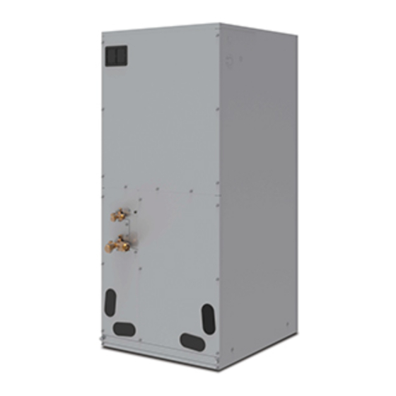
Heat Pump
Air Handlers
Models:
GMH24-36MSK4DH1
GMH48-60MSK4DH1
Please read this owner's manual carefully before operation and retain for future
reference. Specifications & illustrations subject to change without notice or incurring
obligations. If you have lost the owner's manual, please visit www.NortekHVAC.com
for electronic version.
Advertisement
Table of Contents

Related Manuals for Nortek GMH24-36MSK4DH1


Summary of Contents for Nortek GMH24-36MSK4DH1
- Page 1 Installation Instructions Heat Pump Air Handlers Models: GMH24-36MSK4DH1 GMH48-60MSK4DH1 Please read this owner’s manual carefully before operation and retain for future reference. Specifications & illustrations subject to change without notice or incurring obligations. If you have lost the owner’s manual, please visit www.NortekHVAC.com...
- Page 3 To Users Thank you for selecting our product. Please read this instruction manual carefully before installing and using the product, so as to master and correctly use the product. In order to guide you to correctly install and use our product and achieve expected operating effect, we hereby instruct as below: This appliance can be used by children aged from 8 years and above and persons with reduced physical, sensory or mental capabilities or lack of experience and...
- Page 4 Nortek Global HVAC, LLC assumes no responsibility for personal injury, property loss or equipment damage caused by improper installation and commissioning, unnecessary maintenance, or not following relevant national rules and regulations, industrial standards and requirements in this instruction manual. Exception Clauses...
-
Page 5: Table Of Contents
Contents 1 Safety Precautions ............1 2 Product Introduction ............3 2.1 Product Description ..............3 2.2 Optional Accessories..............3 2.3 Physical Dimension ..............4 2.4 Names of Main Parts ..............5 2.5 General Information ...............5 2.6 Dip switch configuration ............5 Performance Data 2.7 Fan ............6 3 Preparative for Installation.......... - Page 6 7.2 Notice before Seasonal Use..........27 7.3 Maintenance after Seasonal Use ......... 27 7.4 Parts Replacement............... 28 8 After-Sales Service ............28 This marking indicates that this product should not be disposed with other household wastes throughout the EU. To prevent possible harm to the environment or human health from uncontrolled waste disposal, recycle it responsibly to promote the sustainable reuse of material resources.
-
Page 7: Safety Precautions
Air Handlers 1 Safety Precautions This product can’t be installed at corrosive, inflammable or explosive environment or the place with special requirements, such as kitchen. Otherwise, it will affect the normal operation or shorten the service life of the unit, or even cause fire hazard or serious injury. - Page 8 Air Handlers Electrical shock hazard: Failure to follow this warning could result in personal injury or death. Before installing, modifying, or servicing system, main electrical disconnect switch must be in the OFF position. There may be more than 1 disconnect switch. Lock out and tag switch with a suitable warning label.
-
Page 9: Product Introduction
6 inches from the solid bottom. 2 Product Introduction 2.1 Product Description The NORTEK air handler offer the perfect combination of superior product quality, operating efficiency, operating sound levels and value for money. The condensing unit uses the environmentally friendly refrigerant R410A, which is chlorine-free to help prevent damage to the ozone layer. -
Page 10: Physical Dimension
Air Handlers 2.3 Physical Dimension Unit: inch(mm) Dimension Model GMH24-36MSK4DH1 21-1/4(540) 21-1/4(540) 48-1/4(1224) 11-5/8(295) 20(508) GMH48-60MSK4DH1 24-3/4(630) 21-1/4(540) 57(1448) 11-5/8(295) 20(508) -
Page 11: Names Of Main Parts
Air Handlers 2.4 Names of Main Parts 2.5 General Information Model Cooling capacity(ton) Optional electric heater (kW) GMH24-36MSK4DH1(24K) 5/8/10 GMH24-36MSK4DH1(36K) 5/8/10 GMH48-60MSK4DH1(48K) 10/15/20 GMH48-60MSK4DH1(60K) 10/15/20 Motor @ 230V ~, 60Hz Model GMH24-36MSK4DH1 GMH48-60MSK4DH1 Unit: mm Model Filter size 490×516×15 GMH24-36MSK4DH1 525×516×15... -
Page 12: Dip Switch Configuration
Model Level Heat (SA2) Cool (SA1) Level 1 Level 2 Level 3 Level 4-Default GMH24-36MSK4DH1(24K) Level 5 Level 6 Level 7 Level 8 Level 1 Level 2 Level 3 Level 4-Default... -
Page 13: Fan Performance Data
External static pressure should stay within the minimum and maximum limits shown in the table below in order to ensure proper operation of both cooling, heating, and electric heating operation. Model GMH24-36MSK4DH1(24K) Static pressure(Inches W.C.) Level 0.15 Speed 1(CFM) 1030... - Page 14 Air Handlers Model GMH24-36MSK4DH1(36K) Static pressure(Inches W.C.) Level 0.15 Speed 1(CFM) 1150 1050 Speed 2(CFM) 1200 1100 1000 Speed 3(CFM) 1380 1260 1200 1100 Speed 4(CFM) 1550 1460 1390 1310 1160 1010 Speed 5(CFM) 1710 1650 1600 1560 1480 1400...
-
Page 15: Preparative For Installation
Air Handlers 3 Preparative for Installation 3.1 Pre-Installation Instruction 3.1.1 Checking Product Received After receiving the product, please check if there is any damage caused by transportation. Shipping damage is the responsibility of the carrier. Verify the model number, specifications and accessories are correct prior to installation. The distributor or manufacturer will not accept claims from dealers for transportation damage or installation of incorrectly shipped units. - Page 16 Air Handlers Immediate hazards which will result in property damage, product damage, severe personal injury or death. Hazards or unsafe practices could result in property damage, product damage, severe personal injury or death. Hazards or unsafe practices which may result in property damage, product damage, severe personal injury or death.
-
Page 17: Installation
Air Handlers Protection Association” (NFPA) 70 and local/state codes. In Canada, electric grounding conforms to the Canadian electric code CSA c22.1. Failure to observe this warning can result in electrical shock that can cause personal injury. Special warning for installation of furnaces or air handling units in enclosed areas, such as garages, utility rooms or parking areas. -
Page 18: Location
Air Handlers If an incorrect unit is supplied, it must not be installed and it is to be returned to the supplier. The manufacturer assumes no responsibility for the installation of incorrectly delivered units. The evaporator coil contains high-pressure inert gas for holding charge. 4.2 Location This air handler is designed for indoor installation only. -
Page 19: Piping Work
4.3 Piping Work 4.3.1 Specification of Connection Pipe External diameter (inch) Model Gas pipe Liquid pipe GMH24-36MSK4DH1 Φ3/4 Φ3/8 GMH48-60MSK4DH1 4.3.2 Piping Preparation 4.3.2.1 Solder Connection All cut ends are to be round, burr free, and cleaned. Failure to follow this practice... - Page 20 Air Handlers...
-
Page 21: Condensate Removal
Air Handlers 4.3.2.2 Screw Connection Pipe diameter (inch) Tightening torque (N·m) Φ1/4 15-30 Φ3/8 35-40 Φ1/2 45-50 Φ5/8 60-65 Φ3/4 70-75 Φ7/8 80-85 4.4 Condensate Removal It is not allowed to connect the condensate drain pipe into waste pipe or other pipelines which are likely to produce corrosive or peculiar smell to prevent the smell from entering indoors or corrupt the unit. -
Page 22: Ductwork
Air Handlers 4.5 Ductwork This air handler is designed for a complete supply and return ductwork system. Field ductwork must meet the National Fire Protection Association NFPA 90A, NFPA 90B and any applicable local ordinance. Sheet metal ductwork run in unconditioned spaces must be insulated and covered with a vapor barrier. - Page 23 Air Handlers Electric heat is available as an accessory. Please refer to installation instructions provided with heater kit for the correct installation procedure. Refer to the “Electric heater kits installation” section of this manual and the instructions provided with the heater kit for the correct installation procedure. The electrical characteristics of the air handler, the electric heater kit, and the supply power should be identical.
- Page 24 Air Handlers 1) Refer to the Table for appropriate heater kit. 2) Check any physical damage, do not install damaged heater kit. 3) Remove the upper access panel from air handler. 4) Remove cover plate from air handler. 5) Slide the heater kit in to the slot and secure element plate with previously removed screws.
-
Page 25: Electrical Installation
Do not change the length and terminals of the power cables. If you want to change the power cables, please contact NORTEK’s local service center. ⑩. Wiring terminals should be connected firmly to the terminal board. Loose... - Page 26 Power supply circuit overcurrent ampacity (A) protection (A) GMH24-36MSK4DH1 208/230V-1Ph-60Hz GMH48-60MSK4DH1 ①. Fuse is located on the main board. ②. Install a circuit breaker at every power terminal near the units (indoor unit and thermostat) with at least 3mm contact gap. The units must be able to be plugged or unplugged.
- Page 27 Air Handlers 4.7.3 Connection of Power Cords and Thermostat Wires For solid wires (as shown below): 1) Use wire cutters to cut off the wire end and then peel away about 25mm of the insulation layer. 2) Use a screwdriver to unscrew the terminal screw on the terminal board. 3) Use nippers to bend the solid wire into a ring that fits the terminal screw.
- Page 28 Air Handlers ①. Before working, please check whether the indoor unit and thermostat are powered on. ②. Match the terminal numbers and wire colors with the colors indicated in the indoor unit. ③. Wrong wire connection may burn the electrical components. ④.
- Page 29 Air Handlers NOTE: Y means Compressor control signal for the outdoor unit; B which is energized under the heating mode means 4-way valve control signal; D means defrosting signal; R means 24V AC power supply; C means 24V common; G means indoor unit fan signal for the indoor unit; W1 means heater control signal.
-
Page 30: Installation Check And Trial Run
Air Handlers 5 Installation Check and Trial Run 5.1 Checking Items after Installation Problems might happen due to Items to be checked Check improper installation Check if each parts of the unit have The unit might fall off, vibrate or emit been installed reliably. -
Page 31: Common Malfunction And Elimination
Air Handlers Check if the unit appearance and piping system has been damaged during transportation or handling. Check if the terminals are loose and the phases are correct. 5.2.2 Trial Run Trial run can be operated by professional personnel only after above items have been checked (items to be checked as per actual condition). - Page 32 Air Handlers NOTE: If reasons are still unclear after checking above items, please contact NORTEK service center and show phenomena and models. Following circumstances are not malfunction. “Malfunction” Reason When unit is started Overload protection switch immediately after it is makes it run after 3 minutes just turned off.
-
Page 33: Maintenance And Care
Air Handlers There are LED indicators on the main board of the indoor unit, which are used to display the operating status and malfunction information of the unit. LED indicator Color Function Indoor unit main board is powered on, Power Indicator Power Indicator is on. - Page 34 Air Handlers Clean the dust of sundries on the indoor units. In the event of rusting, use the anti-rust paint to stop spreading of rust. 7.4 Parts Replacement Purchase parts from local appointed service center or dealer if necessary. When user need to replace the mainboard, installer should put old mainboard jumper cap and the short-driven electrical resistance on the new mainboard.
- Page 36 Specifications & illustrations subject to change without notice or incurring obligations. O’Fallon, MO (03/22) © Nortek Global HVAC, LLC 2022. All Rights Reserved. 797F-0322...
Need help?
Do you have a question about the GMH24-36MSK4DH1 and is the answer not in the manual?
Questions and answers
Filter replacement
To replace the filter for the Nortek GMH24-36MSK4DH1:
1. Cut off the main power supply of the unit.
2. Remove and clean the filter screen of the indoor units.
Note: The context only mentions cleaning the filter, not full replacement instructions. If a replacement is needed, contact the local appointed service center for parts and instructions.
This answer is automatically generated