Table of Contents
Advertisement
Quick Links
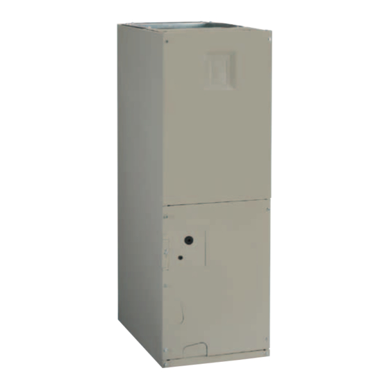
AIR HANDLER
INStALLAtIoN INStRUctIoNS
B6BV SERIES
FoR HUD AppRoVED INStALLAtIoNS IN mANUFActURED HomES AND moDULAR HomES
ImpoRtANt
AttENtIoN INStALLERS:
It is your responsibility to know this product better than your customer. this includes being
able to install the product according to strict safety guidelines and instructing the customer on
how to operate and maintain the equipment for the life of the product. Safety should always be
the deciding factor when installing this product and using common sense plays an important
role as well. pay attention to all safety warnings and any other special notes highlighted in the
manual. Improper installation of the appliance or failure to follow safety warnings could result
in serious injury, death, or property damage.
these instructions are primarily intended to assist qualified individuals experienced in the proper
installation of this appliance. Some local codes require licensed installation/service personnel
for this type of equipment. please read all instructions carefully before starting the installation.
Return these instructions to the customer's package for future reference.
Do Not DEStRoY. pLEASE READ cAREFULLY & KEEp IN A SAFE pLAcE FoR FUtURE REFERENcE.
Advertisement
Table of Contents

Related Manuals for Nortek B6BV Series


Summary of Contents for Nortek B6BV Series
- Page 1 AIR HANDLER INStALLAtIoN INStRUctIoNS B6BV SERIES FoR HUD AppRoVED INStALLAtIoNS IN mANUFActURED HomES AND moDULAR HomES ImpoRtANt AttENtIoN INStALLERS: It is your responsibility to know this product better than your customer. this includes being able to install the product according to strict safety guidelines and instructing the customer on how to operate and maintain the equipment for the life of the product.
-
Page 2: Table Of Contents
UNIt mAINtENANcE ..........11 AIR HANDLER INStALLAtIoN ........ 6 Air Filter(s) ............... 11 Upflow Installations ............6 Figure 7. B6BV Series Air Handler Components ..12 Downflow Installations ............. 6 tRoUBLESHootING ..........12 Plenum Connector Installation ........6 Blower Compartment ............12 A/C or H/P Coil Installation .......... -
Page 3: Important Safety Information
• Verify proper operation after servicing. and create unsafe hazards. Please read all instructions before installing the unit. The B6BV Series air handler is approved for use in HUD REqUIREmENtS & coDES code manufactured homes (HUD Manufactured Home Construction and Safety Standard (Title 24, Part 3280) -
Page 4: Locating The Air Handler
√ Check the electrical supply and verify the power supply INStALLAtIoN cLEARANcES is adequate for unit operation. The system must be wired and provided with circuit protection in accordance with local building codes. If there is any question concerning REAR the power supply, contact the local power company. -
Page 5: Return Air Connections
ASpHYXIAtIoN HAZARD: Do not cover or restrict Air Filters return air opening. B6BV series air handlers are not supplied with an air filter when shipped from the factory. The installer must provide • The return air opening can be located in a closet door or a high velocity filter that is appropriately sized to the return a sidewall. -
Page 6: Air Handler Installation
HVAc technicians should install this air handler. The B6BV series air handler is shipped ready for vertical DOWNFLOW upflow installation and is approved for attic, basement, alcove/closet or crawlspace installation with zero clearance to combustibles. -
Page 7: A/C Or H/P Coil Installation
5. Remove the plenum connector and cut out the marked area of the supply air duct. 18.5" (B-Cab.) 21.25" (C-Cab.) NotE: To allow some clearance for installing the plenum 13.25" connector, cut the opening 1/4” larger the actual cutout drawn. 6. -
Page 8: Electrical Connections
EXpLoSIoN HAZARD • Circuit breakers installed in the B6BV series air handler Failure to follow safety warnings exactly could are for short-circuit protection of the internal wiring result in serious injury or property damage. -
Page 9: Grounding
• The thermostat should be mounted about 5 feet above MOTOR the floor on an inside wall. DO NOT install the thermostat CONTROL BOARD HUMIDISTAT on an outside wall or any other location where its DHUM DHUM operation may be adversely affected by radiant heat from fireplaces, sunlight, or lighting fixtures, and convective heat from warm air registers or electrical appliances. -
Page 10: Air Circulation Check
Selecting Continuous Low Speed Fan Operation B6BV air handlers use high efficiency circulating air motors The B6BV series air handler is equipped with the option The fixed speed motor control board (Figure 12 (page of continuous low speed fan operation. -
Page 11: Selecting Basic Heating Airflow
Please refer to the instructions supplied with the outdoor unit. If icing continues to occur, raise the selected airflow B6BV series air handlers are not supplied with a single air one or two steps. filter when shipped from the factory. It is recommended that the filter be cleaned or replaced monthly. -
Page 12: Troubleshooting
4. motor control Board Fault conditions Heating Element Circuit Assembly Breaker (60A) Transformer Upper Door Assembly Blower Control Wheel Board Capacitor Motor Mount Kit Blower Housing Blower Motor Filter Door Lower Door Assembly Figure 7. B6BV Series Air Handler components... -
Page 13: Figures & Tables
11/8” K.O. (typ.) 1 7/8” 3 5/8” 5 5/8” 13/4” K.O. (typ.) DETAIL “D” “H” 3 1/4” SUCTION 2 1/4” LIQUID 15 1/4” 13” “W” 22" cABINEt SIZE DEtAIL D 49-5/16 19-11/16 18-1/4 55-15/16 22-7/16 Figure 8. B6BV Series physical Dimensions... -
Page 14: Airflow Data
Airflow Data NomINAL ELEctIc HEAt KW cABINEt 1000 1100 1200 1400 1600 1800 2000 table 5. minimum Heating Airflow Settings (in cFm) for B6BV (FSHE) Series Air Handlers B WIDtH cABINEtS NomINAL NomINAL NUmBER oF EXt. StAtIc pRESSURE mEDIUm mEDIUm HIGH BLoWER SIZE motoR SIZE... -
Page 15: Electrical Data & Diagrams
Electrical Data & Diagrams mINImUm cIRcUIt AmpAcItY & mAXImUm oVERcURRENt pRotEctIoN 240 VAc, 50 & 60 HZ, SINGLE pHASE 208 VAc, 50 & 60 HZ, SINGLE pHASE HEAt KIt moDEL cABINEt cApAcItY NUmBER H6HK- 10 Kw 53.6 53.6 47.0 47.0 15 Kw 56.6 25.0 78.6... - Page 16 coNtRoL SIGNAL & moDE opERAtIoN totAL KW BoARD ActIoN Stage 1 Heat on instantly 5 Kw Heat blower on after 3 second delay Stage 1 Heat on instantly 10 Kw Heat blower on after 3 second delay Stage 2 Heat on after 5 seconds delay Stage 1 Heat on instantly Heat blower on after 3 second delay 15 Kw...
- Page 17 coNtRoL SIGNAL & moDE opERAtIoN totAL KW BoARD ActIoN Stage 1 Heat on instantly 5 Kw Cool blower on after 3 second delay Stage 1 Heat on instantly 10 Kw Cool blower on after 3 second delay Stage 2 Heat on after 5 seconds delay Stage 1 Heat on instantly Cool blower on after 3 second delay 15 Kw...
- Page 18 Thermostat Thermostat Thermostat NOTE: Jumper W1 & W2 together if not using W2 on thermostat Conditioner Handler Conditioner Conditioner Y/Y2 Y/Y2 Handler Handler Typical Air Conditioner with Typical Air Conditioner with Typical 2-Stage Air Conditioner Standard Air Handler 2-Stage Air Handler with 2-Stage Air Handler Thermostat Thermostat...
- Page 19 3A Fuse BLWDTC BLWDTC_R COOL HEAT LED 1 HEATER P1 Figure 11. Single Stage control Board POWER EHEAT 1 2 3 4 5 6 7 8 HEAT COOL Figure 12. Fixed Speed motor control Board...
- Page 20 RELAY Figure 13. B6BV Air Handler Equipped With pSc motor & 10 kw Heater Kit (B Size cabinet only)
- Page 21 WIRING DIAGRAM Air Handler with Factory Installed Heat (15kW) NOTES: Remarques 1. The blower motor speed tap connection may 1. Le connecteur de vitesse du moteur du ventilateur peut not be as shown. See the Installation Instructions. différer de l’illustration. Consultez les Instructions d’installation. 2.
- Page 22 WIRING DIAGRAM Air Handler with Factory Installed Heat (20kw) Remarques NOTES: 1. Le connecteur de vitesse du moteur du ventilateur 1. The blower motor speed tap connection may not be peut différer de l’illustration. Consultez les as shown. See the Installation Instructions. Instructions d’installation.
-
Page 24: Installation Check List
Two copies of this manual must be supplied with each air handler when packaged. Specifications & illustrations subject to change without notice or incurring obligations (10/16). O’Fallon, MO, © Nortek Global HVAC LLC 2016. All Rights Reserved. 10163010 (Replaces 709174A)
Need help?
Do you have a question about the B6BV Series and is the answer not in the manual?
Questions and answers