Table of Contents
Advertisement
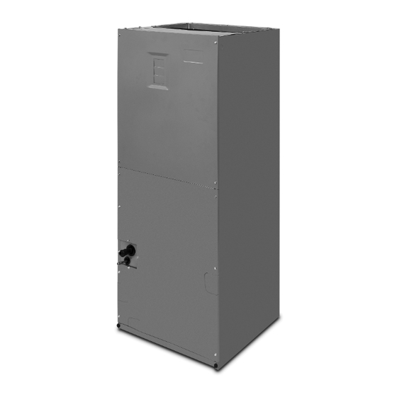
AIR HANDLER
INSTALLATION INSTRUCTIONS
B64BM SERIES
IMPORTANT
ATTENTION INSTALLERS:
It is your responsibility to know this product better than your customer. This includes being
able to install the product according to strict safety guidelines and instructing the customer on
how to operate and maintain the equipment for the life of the product. Safety should always be
the deciding factor when installing this product and using common sense plays an important
role as well. Pay attention to all safety warnings and any other special notes highlighted in the
manual. Improper installation of the furnace or failure to follow safety warnings could result in
serious injury, death, or property damage.
These instructions are primarily intended to assist qualified individuals experienced in the proper
installation of this appliance. Some local codes require licensed installation/service personnel
for this type of equipment. Please read all instructions carefully before starting the installation.
Return these instructions to the customer's package for future reference.
DO NOT DESTROY. PLEASE READ CAREFULLY & KEEP IN A SAFE PLACE FOR FUTURE REFERENCE.
Advertisement
Table of Contents

Related Manuals for Nortek B64BM Series


Summary of Contents for Nortek B64BM Series
- Page 1 AIR HANDLER INSTALLATION INSTRUCTIONS B64BM SERIES IMPORTANT ATTENTION INSTALLERS: It is your responsibility to know this product better than your customer. This includes being able to install the product according to strict safety guidelines and instructing the customer on how to operate and maintain the equipment for the life of the product. Safety should always be the deciding factor when installing this product and using common sense plays an important role as well.
-
Page 2: Table Of Contents
TABLE OF CONTENTS IMPORTANT SAFETY INFORMATION ......3 STARTUP & ADJUSTMENTS ........11 Before You Start the Unit ..........11 REQUIREMENTS & CODES ......... 3 Air Circulation .............. 11 Running the Blower Continuously ....... 11 GENERAL INFORMATION ..........4 Turning the Blower Off ..........11 Before You Install this Unit ........... -
Page 3: Important Safety Information
IMPORTANT SAFETY INFORMATION REQUIREMENTS & CODES INSTALLER: Please read all instructions before servicing this equipment. Pay attention to all safety warnings and WARNING: any other special notes highlighted in the manual. Safety markings are used frequently throughout this manual to This unit must be installed in accordance designate a degree or level of seriousness and should not with instructions outlined in this manual... -
Page 4: General Information
GENERAL INFORMATION Plenums & Air Ducts • Plenums and air ducts should be installed in accordance with This appliance has been tested for capacity and efficiency the standards of the National Fire Protection Association in accordance with AHRI Standards and will provide many Standard for Installation of Air Conditioning Systems years of safe and dependable comfort, providing it is properly (NFPA 90A), Standard for Installation of Residence Type... -
Page 5: Unconditioned Spaces
AIR HANDLER INSTALLATION • Use transition fittings if the supply and/or return air openings of the unit do not match the duct openings. These transitions B64 series air handlers are shipped ready for vertical upflow should be dimensioned in accordance with standard installation and are approved for attic, basement, alcove/closet practice as specified in the ASHRAE recommendations or crawlspace installation with zero clearance to combustibles. -
Page 6: Horizontal Left Installations
NOTE 1: In all horizontal applications in which the unit is installed above a finished ceiling and/or living space, a secondary drain pan must be installed under the entire unit to avoid damage to the ceiling in the event of condensate overflow. -
Page 7: Circuit Breaker Cover Installation
IMPORTANT: If the webbing is not removed, the condensate will not drain properly and ceiling damage may occur. NOTE: It is recommended that the suction line be insulated up to the coil inside of the cabinet. 7. Insert the plug (from horizontal drain pan) into the open and unused drain hole in the drain pan at the bottom of the unit to block bypass air. -
Page 8: Connecting The Linesets
1. Remove the cap from the end of the liquid line. 2. Verify pressurization by depressing the Schrader valve on the end of the liquid line. Listen for any escaping gas. If there is no pressure, test the coil for leakage. •... -
Page 9: Condensate Drainage
5. Connect the suction and liquid lineset tubes. UPFLOW CAUTION: It is recommended that a wet rag be wrapped HORIZONTAL around the suction line in front of the close off plate or the sensing bulb (if TXV is installed) before applying heat. Failure to keep components 3/4”... -
Page 10: Electrical Connections
ELECTRICAL CONNECTIONS wires to the unit and for proper grounding. Field supplied bushings for the power supply cables must be added to WARNING: support and protect the power supply cables. • All 208/230 Volt units are shipped from the factory wired for 240 volt operation. -
Page 11: Line & Low Voltage Connections
condensing unit or heat pump. Twinning is possible for B64 IMPORTANT: Before starting the unit, install the initial units with PSC motors. All low voltage wiring instructions, charge on units that are factory shipped with a nitrogen cautions, and warnings accompanying the air handler remain holding charge: applicable, except for: 1. -
Page 12: 3-Speed Units
UNIT MAINTENANCE 3-Speed Units The blower speed is preset at the factory for operation at the Proper maintenance is most important to achieve the best same speed for heating and cooling, by using the jumping performance from a air handler. Some of the components terminal on the blower motor and connecting it to the desired and their locations are shown in Figure 11 (page... -
Page 13: Refrigerant Charging
CABINET SIZE FILTER SIZE 12 x 20 x 1 18 x 20 x 1 20 x 20 x 1 Filter Sizes Table 3. Blower Fan Wheel - Inspect the blower wheel blades for accumulations of dirt and clean if necessary. Inspect mounting nut for tightness when done. -
Page 14: Figures & Tables
FIGURES & TABLES 3/4” 3/4” 3/4” 13” 11/8” K.O. (typ.) “A” 1 7/8" K.O. 11/4” 15/8” 11/4” 17/8” 3 1/4” 2 5/8” 1 1/8” 1 7/8” 7/8" K.O. 11/8” K.O. (typ.) 1 7/8” 3 5/8” 5 5/8” 13/4” K.O. (typ.) DETAIL “D”... -
Page 15: Drain Pan
Circuit Breaker (60A) Heating Element Assembly Control Motor Control Board Upper Door Board Transformer Assembly Capacitor Blower Blower Wheel Limit Motor Mount Kit Blower Housing Blower Motor Coil Assembly Filter Door Horizontal Drain Pan Vertical Drain Pan Filter Tracks Lower Door Assembly Figure 11. -
Page 16: Airflow Data
Airflow Data DRY COIL ESP *18K Medium A-CABINET High 1064 1007 *24K Medium 1286 1222 1156 1090 1022 A-CABINET High 1362 1293 1224 1153 1082 1010 *24K Medium 1525 1498 1462 1417 1362 1298 1224 1141 B-CABINET High 1846 1779 1709 1635 1557... -
Page 17: Electrical Data & Diagrams
Electrical Data & Diagrams CONTROL SIGNAL & MODE OPERATION TOTAL KW BOARD ACTION Stage 1 Heat on instantly 5 KW Heat blower on after 3 second delay Stage 1 Heat on instantly 10 KW Heat blower on after 3 second delay Stage 1 Heat on instantly 15 KW Heat blower on after 3 second delay... - Page 18 Thermostat Thermostat G R C E NOTE: Jumper between W2 & E is required when Handler no OD T-Stat is used. Handler Conditioner Heat Pump Typical Air Conditioner with Typical Heat Pump with Standard Air Handler Standard Air Handler Typical Thermostat Connections Figure 12.
- Page 19 3A Fuse BLWDTC BLWDTC_R COOL HEAT LED 1 HEATER P1 Single Stage Control Board Figure 14.
- Page 20 WIRING DIAGRAM Air Handler NOTES: 1. The blower motor speed tap connection may not be as shown. See the Installation Instructions. 2. Disconnect all power before servicing. 3. Transformer may have a dual voltage primary tap. Match the tap position with the supply voltage used. 4.
-
Page 24: Installation Checklist
Has the literature package been left near the appliance? Is the thermostat level? Is the heat anticipator setting correct? Specifications & illustrations subject to change without notice or incurring obligations (06/22). 10434200 O’Fallon, MO, © Nortek Global HVAC LLC 2022. All Rights Reserved. (NEW)
Need help?
Do you have a question about the B64BM Series and is the answer not in the manual?
Questions and answers
blower fan comes on with no tstat connected just main power . energize breaker fan runs
blower fan comes on on t stat connected just main power 220 volt