Table of Contents
Advertisement
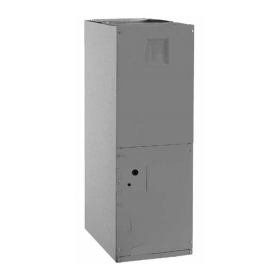
B5BM Series
INSTALLATION INSTRUCTIONS
AIR HANDLER
Please read all information in this manual thoroughly and become familiar with the capabilities
and use of your appliance before attempting to operate or maintain this unit. These instructions
are primarily intended to assist qualified individuals experienced in the proper installation of
this appliance. Some local codes require licensed installation/service personnel for this type
of equipment. Improper installation, service, adjustment, or maintenance may cause explosion,
fire, electrical shock or other hazardous conditions which may result in personal injury or
property damage.
Unless otherwise noted in these instructions, only factory authorized kits or accessories may
be used with this product. Keep this manual where you have easy access to it in the future. If a
problem occurs, check the instructions and follow recommendations given. If these suggestions
don't eliminate your problem, call your servicing contractor.
IMPORTANT
DO NOT DESTROY. PLEASE READ CAREFULLY AND
KEEP IN A SAFE PLACE FOR FUTURE REFERENCE.
Advertisement
Table of Contents

Related Manuals for Nortek B5BM Series


Summary of Contents for Nortek B5BM Series
- Page 1 B5BM Series INSTALLATION INSTRUCTIONS AIR HANDLER IMPORTANT Please read all information in this manual thoroughly and become familiar with the capabilities and use of your appliance before attempting to operate or maintain this unit. These instructions are primarily intended to assist qualified individuals experienced in the proper installation of this appliance.
-
Page 2: Table Of Contents
TABLE OF CONTENTS Startup & Adjustments ..........12 Before You Start the Unit .........12 Important Safety Information ........3 Refrigerant Charging ..........13 Air Circulation ............13 Requirements & Codes ..........3 Running the Blower Continuously ......13 General Information ...........4 Continuous Low Speed Fan Operation ....13 Before You Install this Unit .........4 Turning the Blower Off..........13 Locating the Air Handler ..........4... -
Page 3: Important Safety Information
IMPORTANT SAFETY INFORMATION REqUIREMENTS & CODES INSTALLER: Please read all instructions before servicing WARNING: this equipment. Pay attention to all safety warnings and any other special notes highlighted in the manual. Safety This unit must be installed in accordance with markings are used frequently throughout this manual to instructions outlined in this manual during designate a degree or level of seriousness and should not... -
Page 4: General Information
GENERAL INFORMATION Locating the Air Handler • Survey the job site to determine the best location for This appliance has been tested for capacity and efficiency mounting the unit. Consideration should be given to in accordance with AHRI Standards and will provide availability of electric power, service access, and noise. -
Page 5: Installation In A Garage
handler must be cleaned and/or repaired if found to as the opening provided on the blower coil unit. The be dirty, damaged, or malfunctioning in any way by ducts should be appropriately sized to the capacity of a qualified HVAC technician. The air handler shall be the air handler to ensure its proper airflow rating. -
Page 6: Air Handler Installation
equipment noise eminating from the air handler. These treatments can produce a quieter installation, particularly in the heated space. However, they can increase the pressure drop in the duct system. Care must be taken to maintain the proper maximum pressure rise across the air handler, temperature rise and flow rate. -
Page 7: Horizontal Left Installations
from the factory with all the parts required for horizontal Horizontal Right Installations: left applications and horizontal right applications. If your 1. Remove the coil access door. Unscrew the line-set tube unit does not have parts for a horizontal application, a close-off plate from the front left cabinet rail. -
Page 8: Refrigerant Line Connections
Refrigerant Line Connections CAUTION: WARNING: Before brazing the air handler, remove the core from the service port. Failure to comply may NITROGEN result in leakage at the service valve. Replace HEALTH the core and cap once brazing is complete. FLAMMABILITY REACTIVITY 0 Minimal Hazard 1 Slight Hazard... -
Page 9: Connecting The Linesets
Figure 8. Restrictor Insertion into Distributor Body Figure 6. Loosening of Nut & Distributor Body Connecting the Linesets 6. Insert a light-gauge wire hook between the distributor IMPORTANT NOTES FOR HORIZONTAL OR body and the restrictor orifice while being careful not DOWNFLOW INSTALLATIONS WITH TXV VALVE: to scratch either part. -
Page 10: Condensate Drainage
• Route both lines to a suitable drain, avoiding sharp bends CAUTION: and pinching of the lines. The drain should maintain a minimum horizontal slope in the direction of discharge It is recommended that a wet rag be wrapped of not less than 1” vertical for every 10 ft of horizontal around the suction line in front of the close run. -
Page 11: Electrical Connections
• Use only copper wire for the line voltage power supply ELECTRICAL CONNECTIONS to this unit. Use proper code agency listed conduit and a conduit connector for connecting the supply wires to WARNING: the unit. Aluminum supply wire may be used if a heater kit is installed. -
Page 12: Control Board
STARTUP & ADjUSTMENTS on an outside wall or any other location where its operation may be adversely affected by radiant heat from fireplaces, sunlight, or lighting fixtures, and convective WARNING: heat from warm air registers or electrical appliances. Refer to the thermostat manufacturer’s instruction sheet NITROGEN for detailed mounting and installation information. -
Page 13: Refrigerant Charging
5. Inspect the unit rating plate for the proper type of Minimum Electric Heat Airflow refrigerant and quantity. The minimum electric heat airflow setting controls the 6. Weigh in the proper amount of new (or reclaimed) minimum air flow that will be produced whenever electric refrigerant. -
Page 14: Unit Maintenance
UNIT MAINTENANCE CABINET SIZE FILTER SIZE 12 x 20 x 1 WARNING: 18 x 20 x 1 20 x 20 x 1 ELECTRICAL SHOCK, FIRE OR EXPLOSION Table 1. Filter Sizes HAZARD Failure to follow safety warnings exactly could result in serious injury or property damage. WARNING: Improper servicing could result in dangerous Never operate the air handler without a filter in... -
Page 15: Figures & Tables
FIGURES & TABLES 3/4” 3/4” 3/4” 13” 11/8” K.O. (typ.) “A” 1 7/8" K.O. 11/4” 15/8” 11/4” 17/8” 3 1/4” 2 5/8” 1 1/8” 1 7/8” 7/8" K.O. 11/8” K.O. (typ.) 1 7/8” 3 5/8” 5 5/8” 13/4” K.O. (typ.) DETAIL “D”... - Page 16 Circuit Breaker (60A) Heating Element Assembly Transformer Motor Control Board Blower Control Upper Door Wheel Board Assembly Capacitor Motor Mount Kit Blower Housing Blower Coil Motor Assembly Filter Door Horizontal Vertical Drain Pan Drain Pan Filter Tracks Lower Door Assembly Figure 11.
-
Page 17: Airflow Data
AIRFLOW DATA Dry Coil ESP 0.10 0.20 0.30 0.40 0.50 0.60 0.70 0.80 Corrected ESP 0.00 0.07 0.19 0.30 0.42 0.53 0.65 0.76 Medium *24K A-Cabinet Corrected ESP 0.00 0.00 0.11 0.23 0.36 0.48 0.60 0.72 High 1072 1026 Corrected ESP 0.00 0.00 0.00... -
Page 18: Electrical Diagrams
ELECTRICAL DIAGRAMS Thermostat Thermostat Thermostat NOTE: Jumper W1 NOTE: Jumper W1 NOTE: Jumper W1 &W2 together for &W2 together for &W2 together for shorter staging time. shorter staging time. shorter staging time. Conditioner Conditioner Conditioner Y/Y2 Y/Y2 Y/Y2 Handler NOTE: For AC applications, the O & Y Handler connection must be connected as shown. - Page 19 G Y/Y2 O W1 W2 Y1 FUSE 24VAC L2COM L1/VSPOWER XFMR X13 COOL X13 HEAT X13 COM Figure 13. Motor Control Board...
- Page 20 Figure 14. Wiring Diagram for B5BM Series Air Handler (Variable Speed)
- Page 21 TRANSFORMER RED/BLACK GREY 1=LOW C=COM 2=MED LO L=LINE 3=MED BLACK G=GROUND 4=MED HI N=NEUTRAL 5=HI WHITE LEGEND: ¢710545$¤ FIELD WIRING 710545B LOW VOLTAGE (Replaces 710545A) HIGH VOLTAGE 0310 Figure 15. Wiring Diagram for B5BM Series Air Handler with X-13 Motor...
- Page 22 Figure 16. Wiring Diagram for B5BM Series Air Handler (8kW & 10 kW)
- Page 23 Figure 17. Wiring Diagram for B5BM Series Air Handler with X-13 Motor (8kW & 10 kW)
- Page 24 Figure 18. Wiring Diagram for B5BM Series Air Handler (15kW)
- Page 25 Figure 19. Wiring Diagram for B5BM Series Air Handler with X-13 Motor (20 kW)
-
Page 26: Electrical Data
ELECTRICAL DATA Standard Air Handler (A & B Size) Standard Air Handler (C Size) Auxillary ***MAC ***MAC Voltage Heat Installed (Nom. KW) Circuit Circuit Circuit Circuit Single Single Single Single Circuit Circuit Circuit Circuit NONE 005H 008H 010H 015H 14.4 020H 19.2 025H... -
Page 28: Installation / Performance Checklist
INSTALLATION / PERFORMANCE CHECK LIST ELECTRICAL SYSTEM: ATTENTION INSTALLERS: Electrical connections tight? It is your responsibility to know this product better than your customer. This includes being able to install the product according to strict Line voltage polarity correct? safety guidelines and instructing the customer on how to operate and maintain the equipment for the life of the product.
Need help?
Do you have a question about the B5BM Series and is the answer not in the manual?
Questions and answers