Nortek B6BM Series Installation Instructions Manual
Hide thumbs
Also See for B6BM Series:
- Installation instructions manual (32 pages) ,
- Installation instructions manual (32 pages)
Table of Contents
Advertisement
Quick Links
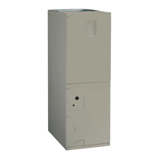
AIR HANDLER
INStALLAtIoN INStRuctIoNS
B6BM, B6EM, & B6VM SERIES
IMPoRtANt
AttENtIoN INStALLERS:
It is your responsibility to know this product better than your customer. this includes being
able to install the product according to strict safety guidelines and instructing the customer on
how to operate and maintain the equipment for the life of the product. Safety should always be
the deciding factor when installing this product and using common sense plays an important
role as well. Pay attention to all safety warnings and any other special notes highlighted in the
manual. Improper installation of the furnace or failure to follow safety warnings could result in
serious injury, death, or property damage.
these instructions are primarily intended to assist qualified individuals experienced in the proper
installation of this appliance. Some local codes require licensed installation/service personnel
for this type of equipment. Please read all instructions carefully before starting the installation.
Return these instructions to the customer's package for future reference.
Do Not DEStRoY. PLEASE READ cAREFuLLY & KEEP IN A SAFE PLAcE FoR FutuRE REFERENcE.
Advertisement
Table of Contents

Related Manuals for Nortek B6BM Series


Summary of Contents for Nortek B6BM Series
- Page 1 AIR HANDLER INStALLAtIoN INStRuctIoNS B6BM, B6EM, & B6VM SERIES IMPoRtANt AttENtIoN INStALLERS: It is your responsibility to know this product better than your customer. this includes being able to install the product according to strict safety guidelines and instructing the customer on how to operate and maintain the equipment for the life of the product.
-
Page 2: Table Of Contents
tABLE oF coNtENtS IMPoRtANt SAFEtY INFoRMAtIoN ......3 StARtuP & ADjuStMENtS ........11 Before You Start the Unit ..........11 REquIREMENtS & coDES ......... 3 Air Circulation .............. 12 Running the Blower Continuously ......12 GENERAL INFoRMAtIoN ..........4 Selecting Continuous Low Speed Fan Operation ..12 Before You Install this Unit ........... -
Page 3: Important Safety Information
IMPoRtANt SAFEtY INFoRMAtIoN REquIREMENtS & coDES INSTALLER: Please read all instructions before servicing this equipment. Pay attention to all safety warnings and WARNING: any other special notes highlighted in the manual. Safety markings are used frequently throughout this manual to this unit must be installed in accordance designate a degree or level of seriousness and should not with instructions outlined in this manual... -
Page 4: General Information
GENERAL INFoRMAtIoN Plenums & Air Ducts • Plenums and air ducts should be installed in accordance with This appliance has been tested for capacity and efficiency the standards of the National Fire Protection Association in accordance with AHRI Standards and will provide many Standard for Installation of Air Conditioning Systems years of safe and dependable comfort, providing it is properly (NFPA 90A), Standard for Installation of Residence Type... -
Page 5: Unconditioned Spaces
AIR HANDLER INStALLAtIoN • Use transition fittings if the supply and/or return air openings of the unit do not match the duct openings. These transitions B6 series air handler’s are shipped ready for vertical upflow should be dimensioned in accordance with standard installation and are approved for attic, basement, alcove/closet practice as specified in the ASHRAE recommendations or crawlspace installation with zero clearance to combustibles. -
Page 6: Horizontal Left Installations
to avoid damage to the ceiling in the event of condensate overflow. Additionally, it is recommended that an approved water level indicator or float switch device be used to shut down the unit in the event water is detected in the auxiliary drain pan. -
Page 7: Circuit Breaker Cover Installation
NotE: It is recommended that the suction line be insulated up to the coil inside of the cabinet. 7. Insert the plug (from horizontal drain pan) into the open and unused drain hole in the drain pan at the bottom of the unit to block bypass air. -
Page 8: Connecting The Linesets
1. Remove the cap from the end of the liquid line. 2. Verify pressurization by depressing the Schrader valve on the end of the liquid line. Listen for any escaping gas. If there is no pressure, test the coil for leakage. •... -
Page 9: Condensate Drainage
5. Connect the suction and liquid lineset tubes. UPFLOW cAutIoN: It is recommended that a wet rag be wrapped HORIZONTAL around the suction line in front of the close off plate or the sensing bulb (if tXV is installed) before applying heat. Failure to keep components 3/4”... -
Page 10: Electrical Connections
ELEctRIcAL coNNEctIoNS • If replacing any of the original wires supplied with the unit, the replacement wire must be copper wire consisting of WARNING: the same gauge and temperature rating. • Provide power supply for the unit in accordance with the unit wiring diagram, and the unit rating plate. -
Page 11: Twinning
Figure 15 (page 26) Figure 16 (page 26) MOTOR Table 13A, (page 22), Table 13B, (page 23), & Table CONTROL BOARD HUMIDISTAT 13C, (page 24) for control board modes and actions. DHUM DHUM twinning These instructions are to be used when connecting two B5 or B6 air handlers (2-5 ton models) to a common single stage A/C condensing unit or heat pump. -
Page 12: Air Circulation
Air circulation Blower configurations Running the Blower Continuously Determining Nominal System Capacity Set the thermostat’s system mode to oFF and the thermostat’s To select the appropriate airflows for the air handler, the fan mode to oN. The blower motor should run continuously. nominal system capacity must be known. -
Page 13: Basic Heating Airflow For Variable & Fixed Speed
change speeds during start-up, shut down, when thermostat inputs change, and when the duct static pressure changes tRouBLESHootING (vents closed or opened, filter clogging, etc.). The air handler If the air handler fails to operate, check the following: is configured by setting the selector switches and removing •... -
Page 14: Unit Maintenance
refer to Table 3 Table 4 to determine fault condition. cABINEt SIZE FILtER SIZE uNIt MAINtENANcE 12 x 20 x 1 Proper maintenance is most important to achieve the best 18 x 20 x 1 performance from a air handler. Some of the components 20 x 20 x 1 and their locations are shown in Figure 12 (page... -
Page 15: Figures & Tables
FIGuRES & tABLES 3/4” 3/4” 3/4” 13” 11/8” K.O. (typ.) “A” 1 7/8" K.O. 11/4” 15/8” 11/4” 17/8” 3 1/4” 2 5/8” 1 1/8” 1 7/8” 7/8" K.O. 11/8” K.O. (typ.) 1 7/8” 3 5/8” 5 5/8” 13/4” K.O. (typ.) DETAIL “D”... - Page 16 Circuit Breaker (60A) Heating Element Assembly Control Motor Control Board Upper Door Board Transformer Assembly Blower Capacitor Wheel Motor Mount Kit Blower Housing Blower Motor Coil Assembly Filter Door Horizontal Drain Pan Vertical Drain Pan Filter Tracks Lower Door Assembly Figure 12.
-
Page 17: Airflow Data
Airflow Data DRY coIL ESP 0.10 0.20 0.30 0.40 0.50 0.60 0.70 0.80 Corrected ESP 0.00 0.07 0.19 0.30 0.42 0.53 0.65 0.76 Medium *24K A-cABINEt Corrected ESP 0.00 0.00 0.11 0.23 0.36 0.48 0.60 0.72 High 1072 1026 Corrected ESP 0.00 0.00 0.00... - Page 18 cooLING oR HEAtING AIRFLoW (cFM) SWItcH SEttINGS 0 = oFF, 1 = oN DRY coIL ESP — — 1030 B6EM 1115 1085 1060 1020 A-cABINEt 1155 1130 1095 1070 1040 1010 1200 1175 1145 1110 1085 1060 1025 1000 1240 1215 1195 1170...
-
Page 19: Settings (Cfm)
NoMINAL ELEctIc HEAt KW cABINEt 1000 1300 1000 1050 1100 1300 1500 1000 1100 1150 1200 1400 1600 1800 2000 NotE: See Table 7, (page 18) for appropriate switch settings for these airflows. B6EM (FSHE) Minimum Heating Airflow Settings (cFM) table 8. - Page 20 cooLING AIRFLoW HEAtING AIRFLoW cooL SWItcH SEttING A/B SWItcH SEttING AIRFLoW A/B SWItcH SEttING HEAtER KIt AIRFLoW 0 = oFF, 1 = oN 0 = oFF, 1 = oN (cFM) 0 = oFF, 1 = oN INStALLED (KW) (cFM) 1000 1000 1300 B6VM...
-
Page 21: Electrical Data & Diagrams
Electrical Data & Diagrams B6BM MINIMuM cIRcuIt AMPAcItY & MAXIMuM oVERcuRRENt PRotEctIoN 240 VAc, 50 & 60 HZ, SINGLE PHASE 208 VAc, 50 & 60 HZ, SINGLE PHASE HEAt KIt MoDEL cABINEt cAPAcItY NuMBER H8HK- NONE 005H-XX 26.6 26.6 23.3 23.3 008H-XX 41.2... - Page 22 B6(E,V)M MINIMuM cIRcuIt AMPAcItY & MAXIMuM oVERcuRRENt PRotEctIoN 240 VAc, 50 & 60 HZ, SINGLE PHASE 208 VAc, 50 & 60 HZ, SINGLE PHASE HEAt KIt MoDEL cABINEt cAPAcItY NuMBER H8HK- NONE 005H-XX 29.5 29.5 26.4 26.4 008H-XX 44.1 44.1 39.1 39.1 24/30...
- Page 23 coNtRoL SIGNAL & MoDE oPERAtIoN totAL KW BoARD ActIoN Stage 1 Heat on instantly 5 KW Heat blower on after 3 second delay Stage 1 Heat on instantly 10 KW Heat blower on after 3 second delay Stage 2 Heat on after 5 seconds delay Stage 1 Heat on instantly Heat blower on after 3 second delay 15 KW...
- Page 24 coNtRoL SIGNAL & MoDE oPERAtIoN totAL KW BoARD ActIoN Stage 1 Heat on instantly 5 KW Cool blower on after 3 second delay Stage 1 Heat on instantly 10 KW Cool blower on after 3 second delay Stage 2 Heat on after 5 seconds delay Stage 1 Heat on instantly Cool blower on after 3 second delay 15 KW...
- Page 25 Thermostat Thermostat Thermostat NOTE: Jumper W1 & W2 together if not using W2 on thermostat Conditioner Handler Conditioner Conditioner Y/Y2 Y/Y2 Handler Handler Typical Air Conditioner with Typical Air Conditioner with Typical 2-Stage Air Conditioner Standard Air Handler 2-Stage Air Handler with 2-Stage Air Handler Thermostat Thermostat...
- Page 26 3A Fuse BLWDTC BLWDTC_R COOL HEAT LED 1 HEATER P1 Single Stage control Board Figure 15. LED 1 HEATER P1 two - Stage control Board Figure 16.
- Page 27 POWER EHEAT 1 2 3 4 5 6 7 8 HEAT COOL Fixed Speed Motor control Board Figure 17. STATUS LIGHTS L2-IN L2-OUT Y/Y2 L1-IN L1-OUT DEHUM FAN SPEED 2 3 4 5 6 7 8 TEST PORT COOL HEAT SENSOR EXPANSION PORT BLOWER MOTOR...
- Page 28 WIRING DIAGRAM Air Handler Remarques NOTES: 1. Le connecteur de vitesse du moteur du ventilateur peut 1. The blower motor speed tapconnection may not be as shown. différer de l’illustration. Consultez les Instructions See the Installation Instructions. d’installation. 2. Disconnect all power beforeservicing. 2.
- Page 29 WIRING DIAGRAM Air Handler with Fixed Speed High Efficiency Motor Remarques NOTES: 1. Le connecteur de vitesse du moteur du ventilateur 1. The blower motor speed tap connection may not be peut différer de l’illustration. Consultez les as shown. See the Installation Instructions. Instructions d’installation.
- Page 30 WIRING DIAGRAM Air Handler with Variable Speed High Efficiency Motor Remarques 1. Le connecteur de vitesse du moteur du ventilateur peut NOTES: différer 1. The blower motor speed tap connection may not be as shown. de l’illustration. Consultez les Instructions d’installation. See the Installation Instructions.
-
Page 32: Installation Checklist
WARNING: this product contains chemicals known to the state of california to cause birth defects or other reproductive harm. Specifications & illustrations subject to change without notice or incurring obligations (02/17). 1016108A (Replaces 10161080) O’Fallon, MO, © Nortek Global HVAC LLC 2017. All Rights Reserved.
Need help?
Do you have a question about the B6BM Series and is the answer not in the manual?
Questions and answers