Table of Contents
Advertisement
Quick Links
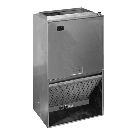
B64EW Series
INSTALLATION INSTRUCTIONS
Vertical Wall Mount Air Handler
Please read all information in this manual thoroughly and become familiar with the capabilities
and use of your appliance before attempting to operate or maintain this unit. These instructions
are primarily intended to assist qualified individuals experienced in the proper installation of
this appliance. Some local codes require licensed installation/service personnel for this type
of equipment. Improper installation, service, adjustment, or maintenance may cause explosion,
fire, electrical shock or other hazardous conditions which may result in personal injury or
property damage.
Unless otherwise noted in these instructions, only factory authorized kits or accessories may
be used with this product. Keep this manual where you have easy access to it in the future. If a
problem occurs, check the instructions and follow recommendations given. If these suggestions
don't eliminate your problem, call your servicing contractor.
NOTE: Unit style may appear different depending on model.
IMPORTANT
DO NOT DESTROY. PLEASE READ CAREFULLY AND
KEEP IN A SAFE PLACE FOR FUTURE REFERENCE.
Advertisement
Table of Contents

Related Manuals for Nortek B64EW Series


Summary of Contents for Nortek B64EW Series
- Page 1 B64EW Series INSTALLATION INSTRUCTIONS Vertical Wall Mount Air Handler NOTE: Unit style may appear different depending on model. IMPORTANT Please read all information in this manual thoroughly and become familiar with the capabilities and use of your appliance before attempting to operate or maintain this unit. These instructions are primarily intended to assist qualified individuals experienced in the proper installation of this appliance.
-
Page 2: Important Safety Information
TABLE OF CONTENTS IMPORTANT SAFETY INFORMATION INSTALLER: Please read all instructions before servicing Important Safety Information ........2 this equipment. Pay attention to all safety warnings and any other special notes highlighted in the manual. Safety Requirements & Codes ..........3 markings are used frequently throughout this manual to General Information ...........4 designate a degree or level of seriousness and should not be ignored. -
Page 3: Requirements & Codes
REQUIREMENTS & CODES • Air handler installations in a residential garage must be installed as specified on page WARNING: The information listed below is for reference purposes only This unit must be installed in accordance with and does not necessarily have jurisdiction over local or state instructions outlined in this manual during codes. -
Page 4: General Information
GENERAL INFORMATION Locating the Air Handler • Survey the job site to determine the best location for The unit has been tested and certified by AHRI for capacity mounting the unit. Consideration should be given to and efficiency and will provide many years of safe and availability of electric power, service access, and noise. - Page 5 must be cleaned and/or repaired if found to be dirty, • Design the duct work according to methods described damaged, or malfunctioning in any way by a qualified by the Air Conditioning Contractors of America (ACCA). HVAC technician. The air handler shall be inspected •...
-
Page 6: Air Handler Installation
AIR HANDLER INSTALLATION Packaging Removal Remove the shipping crate and User’s Manual from The B64EW Air Handler is shipped ready for vertical the equipment. Take care not to damage the tubing upflow installation and can be mounted directly on a wall connections when removing the crate. - Page 7 Connecting Refrigerant Tubing CAUTION: WARNING: This unit uses refrigerant R-410A. DO NOT use any other refrigerant in this unit. Use of another NITROGEN refrigerant will damage the unit. HEALTH • Every effort should be made by the installer to ensure FLAMMABILITY that the field installed refrigerant containing components of the system have been installed in accordance with...
- Page 8 • Always refer to the installation instructions supplied with 3. Braze the individual connections with dry nitrogen the outdoor unit for piping requirements. The suction flowing through the joints. This will prevent internal and liquid lines must be sized in accordance with the oxidation and scaling from occurring.
-
Page 9: Electrical Wiring
• Both adapters should be made of PVC or similar material ELECTRICAL WIRING and contain a rubber washer. Hand tighten the adapters to the drain pan. DO NOT use pliers or any other tools. WARNING: Overtightening may crack the drain pan and cause condensate to leak. - Page 10 • If replacing any of the original wires supplied with the unit, the replacement wire must be copper wire consisting Thermostat of the same gauge and temperature rating. G R W • Provide power supply for the unit in accordance with the unit wiring diagram, and the unit rating plate.
- Page 11 Configuring Blower Speed for Multi-Speed Units 5 Speed Motor Terminals The blower speed is preset at the factory for operation Terminal M1 = Low speed at the same speed for heating and cooling, by using the Terminal M2 = Medium Low speed jumping terminal on the blower motor and connecting it Terminal M3 = Medium speed to the desired speed with both the red and black wires...
-
Page 12: Startup & Adjustments
STARTUP & ADJUSTMENTS 5. Inspect the mating units rating plate and installation instructions for the proper type of refrigerant and quantity. WARNING: 6. Refer to mating units installation instructions for determination of the proper refrigerant charge amount and its application. NITROGEN 7. -
Page 13: Unit Maintenance
UNIT MAINTENANCE Model Number Filter Size Proper maintenance is most important to achieve the best B64EW-X18K performance from an air handler. Follow these instructions 16” x 20 x 1” B64EW-X24K for years of safe, trouble free operation. B64EW-X30K 20” x 20 x 1” WARNING: B64EW-X36K 24”... - Page 14 FIGURES & TABLES 1 5/8 1 5/8 VIEW 1 7/8 Liquid Line Ø3/8" Low Voltage 2 1/8 Ø1 1/8" K.O. Suction 1 1/4 Power Entry Line Ø1 1/8" K.O. 1 1/2 Power Entry 1 5/8 2 5/8 Ø3/8" K.O. 6 1/4 10 1/2 1 1/2 LEFT...
-
Page 15: Airflow Data
AIRFLOW DATA DRY COIL ESP X18K-05 1,041 1,014 1,180 1,155 1,130 1,104 1,078 1,052 1,026 X18K-08 1,041 1,014 1,180 1,155 1,130 1,104 1,078 1,052 1,026 X24K-05 1,041 1,014 1,180 1,155 1,130 1,104 1,078 1,052 1,026 X24K-08 1,041 1,014 1,180 1,155 1,130 1,104 1,078... - Page 16 AIRFLOW DATA CONTINUED DRY COIL ESP X36K-05 1,236 1,202 1,165 1,126 1,085 1,042 1,326 1,289 1,251 1,212 1,174 1,134 1,094 1,053 1,380 1,347 1,312 1,276 1,239 1,200 1,161 1,121 X36K-08 1,236 1,202 1,165 1,126 1,085 1,042 1,326 1,289 1,251 1,212 1,174 1,134 1,094...
-
Page 17: Wiring Diagrams
WIRING DIAGRAMS TO THERMOSTAT Figure 6. Wiring Diagram for B64EW-X18K, B64EW-X24K, B64EW-X30K, & B64EW-X36K (1.5, 2, 2.5, & 3 Ton Units) - Page 18 TO THERMOSTAT Figure 7. Wiring Diagram for B64EW-X18K, B64EW-X24K, B64EW-X30K, & B64EW-X36K (1.5, 2, 2.5, & 3 Ton Units)
- Page 19 LOCATION OF AIR HANDLER COMPONENTS Heating Element Mounting Assembly Bracket Element Relay Limit Switch Circuit Breaker (60A) Distributor Coil Assembly Blower Motor Drain Pan Motor Mount Blower Housing PCB Board Transformer Blower Wheel Figure 8. Air Handler Components...
-
Page 20: Installation Checklist
Please read all instructions carefully before starting the installation. Return these instructions to the customer’s package for future reference. 10456250 Specifications & illustrations subject to change without notice or incurring obligations (07/23). (NEW) O’Fallon, MO, © Nortek Global HVAC LLC 2023. All Rights Reserved.
Need help?
Do you have a question about the B64EW Series and is the answer not in the manual?
Questions and answers