Fluke 116 User Manual
True-rms multimeter
Hide thumbs
Also See for 116:
- User manual ,
- Specifications (2 pages) ,
- Calibration information manual (26 pages)
Table of Contents

Related Manuals for Fluke 116


Summary of Contents for Fluke 116
- Page 1 True-rms Multimeter Users Manual July 2006 Rev. 2, 5/21 (English) © 2006-2021 Fluke Corporation. All rights reserved. Specifications are subject to change without notice. All product names are trademarks of their respective companies.
- Page 2 Fluke authorized resellers shall extend this warranty on new and unused products to end-user customers only but have no authority to extend a greater or different warranty on behalf of Fluke. Warranty support is available only if product is purchased through a Fluke authorized sales outlet or Buyer has paid the applicable international price.
-
Page 3: Table Of Contents
Table of Contents Title Page Introduction ....................Contact Fluke .................... Safety Information ..................Unsafe Voltage..................Display ...................... Terminals ....................Error Messages..................Rotary Switch Positions ................Battery Saver™ (Sleep Mode) ..............MIN MAX AVG Recording Mode............... Display HOLD ................... Backlight....................Manual and Autoranging ................ - Page 4 Users Manual...
-
Page 5: Introduction
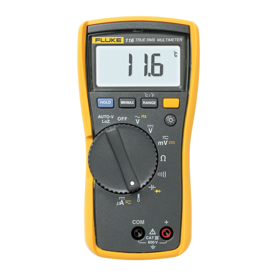
Introduction The Fluke Model 116, is a battery-powered, true-rms multimeter (the Meter or Product) with a 6000-count display and a bar graph. Contact Fluke Fluke Corporation operates worldwide. For local contact information, go to our website: www.fluke.com To register your product, view, print, or download the latest manual or manual supplement, go to our website. -
Page 6: Display
Users Manual Display Table 1 shows the areas of the display. Table 1. Display Item Symbol Description The Meter function is set to Continuity. The Meter function is set to Diode Test Input is a negative value. X Unsafe voltage. -
Page 7: Terminals
True-rms Multimeter Terminals Terminals Table 2 is a list of terminals on the Meter. Table 2. Terminals Description Common (return) terminal for all measurements. Input terminal for all measurements. Error Messages Table 3 is a list of error messages for the Meter. Table 3. -
Page 8: Rotary Switch Positions
Users Manual Rotary Switch Positions Table 4 is a list of the rotary switch positions and features. Table 4. Features Switch Position Measurement Function The Meter is turned off. Automatically selects ac or dc volts based on the sensed input with a low impedance input. -
Page 9: Min Max Avg Recording Mode
True-rms Multimeter MIN MAX AVG Recording Mode MIN MAX AVG Recording Mode The MIN MAX AVG recording mode captures the minimum and maximum input values (ignoring overloads), and calculates a running average of all readings. When the Meter detects a new high or low, the Meter beeps. -
Page 10: Manual And Autoranging
Users Manual Manual and Autoranging The Meter has both Manual and Autorange modes. The Meter defaults to Autorange. To toggle between Manual and Autorange, push for 1 second. • In the Autorange mode, the Meter selects the range with the best resolution. •... -
Page 11: Making Basic Measurements
True-rms Multimeter Making Basic Measurements Making Basic Measurements When connecting the test leads to the circuit or device, connect the common (COM) test lead before connecting the live lead; when removing the test leads, remove the live lead before removing the common test lead. XW Warning To prevent electric shock, injury, or damage to the Meter, disconnect circuit power and discharge all high-voltage capacitors before testing resistance,... -
Page 12: Measuring Ac And Dc Voltage
Users Manual Measuring AC and DC Voltage V ac V dc Using Auto Volts Selection With the function switch in the x position, the Meter automatically selects a dc or ac voltage measurement based on the input applied between the V or + and COM jacks. This function also sets the Meter’s input impedance to approximately 3 kΩ... -
Page 13: Measuring Ac Or Dc Current
True-rms Multimeter Making Basic Measurements Measuring AC or DC Current XW Warning To avoid personal injury or damage to the Meter: • Never attempt to make an in-circuit current measurement when the open-circuit potential to earth is >600 V. • Use the proper terminals, switch position, and range for your measurement. -
Page 14: Measuring Capacitance
Users Manual Measuring Capacitance Measuring Temperature XW Warning To prevent risk of electric shock, do NOT connect 80BK to live circuits. 80BK Type K... -
Page 15: Measuring Frequency
True-rms Multimeter Making Basic Measurements Measuring Frequency XW Warning To prevent electrical shock, disregard the bar graph for frequencies >1 kHz. If the frequency of the measured signal is >1 kHz, the bar graph and Z are unspecified. The Meter measures the frequency of a signal by counting the number of times the signal crosses a trigger level each second. -
Page 16: Testing Diodes
Users Manual Testing Diodes... -
Page 17: Measuring Current Above 600 Μa
Current Probe to measure currents that exceed the rating of the Meter. Make sure the Meter has the correct function, AC or DC, selected for your current probe. Refer to a Fluke catalog or contact your local Fluke representative for compatible current clamps. -
Page 18: Maintenance
Users Manual Maintenance Maintenance of the Meter consists of battery replacement and case cleaning. Replacing the Battery XW Warning To prevent shock, injury, or damage to the Meter, remove test leads from the Meter before opening the case or battery door. Figure 1 for disassembly. -
Page 19: Specifications
Accuracy is specified for 1 year after calibration, at operating temperatures of 18 °C to 28 °C, with relative humidity at 0 % to 90 %. Extended specifications are available at www.fluke.com. Maximum voltage between any terminal and earth ground......600 V Display Digital .........................6000 counts, updates 4/s... - Page 20 Users Manual Table 6. Accuracy Specifications Accuracy Function Range Resolution ± ([% of Reading] + [Counts]) DC Millivolts 600.0 mV 0.1 mV 0.5 % + 2 6.000 V 0.001 V DC Volts 60.00 V 0.01 V 0.5 % + 2 600.0 V 0.1 V DC, 45 to 500 Hz...
- Page 21 True-rms Multimeter Specifications Table 6. Accuracy Specifications (cont.) Accuracy Function Range Resolution ± ([% of Reading] + [Counts]) 99.99 Hz 0.01 Hz 999.9 Hz 0.1 Hz 0.1 % + 2 Hz (V or A input) 9.999 kHz 0.001 kHz 50.00 kHz 0.01 kHz Notes: [1] All ac ranges except Auto-V LoZ are specified from 1 % to 100 % of range.
- Page 22 Users Manual...
Need help?
Do you have a question about the 116 and is the answer not in the manual?
Questions and answers