Table of Contents
Advertisement
Quick Links
Test Equipment Depot - 800.517.8431 - 99 Washington Street Melrose, MA 02176 - TestEquipmentDepot.com
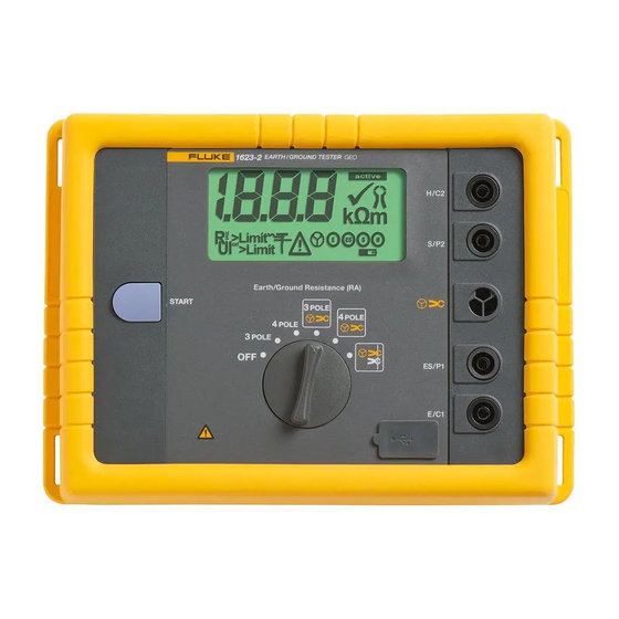
1623-2
Earth/Ground Tester
Users Manual
January 2014
© 2014 Fluke Corporation. All rights reserved. Specifications are subject to change without notice.
All product names are trademarks of their respective companies.
Advertisement
Table of Contents

Related Manuals for Fluke 1623-2


Summary of Contents for Fluke 1623-2
- Page 1 Test Equipment Depot - 800.517.8431 - 99 Washington Street Melrose, MA 02176 - TestEquipmentDepot.com 1623-2 Earth/Ground Tester Users Manual January 2014 © 2014 Fluke Corporation. All rights reserved. Specifications are subject to change without notice. All product names are trademarks of their respective companies.
- Page 2 Fluke authorized resellers shall extend this warranty on new and unused products to end-user customers only but have no authority to extend a greater or different warranty on behalf of Fluke. Warranty support is available only if product is purchased through a Fluke authorized sales outlet or Buyer has paid the applicable international price.
-
Page 3: Table Of Contents
Table of Contents Title Page Introduction ......................1 How to Contact Fluke ..................1 Safety Information ....................2 Storage ....................... 3 Models and Accessories ..................4 Additional Accessories ..................5 Features ......................6 Display ....................... 7 Setup ........................8 Batteries ......................8 Description of Functions ................ - Page 4 1623-2 Users Manual...
-
Page 5: List Of Tables
List of Tables Table Title Page Symbols ........................3 Models and Accessories ..................4 Features and Functions ..................6 Display ........................7 Sample .CSV File for Logged Data ................ 26 Troubleshooting ...................... 27... - Page 6 1623-2 Users Manual...
-
Page 7: List Of Figures
List of Figures Figure Title Page External Current Transformer EI-162BN ..............5 Battery Insertion ..................... 9 2-Pole Measurement ..................12 3-Pole Measurement ..................12 4-Pole Measurements ..................14 3-Pole Selective Earth Resistance Measurement with Current Clamp ..... 16 4-Pole Selective Earth Resistance with Current Clamp ........18 Stakeless Ground Loop Measurement .............. - Page 8 1623-2 Users Manual...
-
Page 9: Introduction
Introduction The 1623-2 Earth Ground Tester (Tester or Product) is a compact, field-rugged instrument that performs all four types of earth ground measurement. Specifically, the Tester is able to measure earth ground loop resistances using only clamps – called Stakeless testing. This method doesn’t require the use of earth ground stakes or the disconnection of ground rods. -
Page 10: Safety Information
1623-2 Users Manual Safety Information A Warning identifies hazardous conditions and procedures that are dangerous to the user. A Caution identifies conditions and procedures that can cause damage to the Product or the equipment under test. Warning To prevent possible electrical shock, fire, or personal injury: •... -
Page 11: Storage
9 "Monitoring and Control Instrumentation” product. Do not dispose of this product as unsorted municipal waste. Go to Fluke’s website for recycling information. Storage If the Tester is stored for an extended period of time or is not in use for a long time, you... -
Page 12: Models And Accessories
ES-162P4-2 Stake Set for 4 Pole Measurement (Includes 4 Earth Stakes, 1 Cable Reel 25M Blue, 1 Cable Reel 25M Green, 1 Cable Reel 50M Red) 4359389 EI-1623 Selective/Stakeless Clamp Set for 1623-2/1625-2 (Includes EI-162X, EI-162AC) 2577115 EI-162X Clip-on Current Transformer (sensing) with shielded cable... -
Page 13: Additional Accessories
Earth/Ground Tester Additional Accessories Additional Accessories An external current transformer is available as an option, see Figure 1. The transformer has a transformation ratio between 80 and 1200:1 for the measurement of a single branch in mesh-operated earthing systems. This enables the user to measure on high voltage pylons without separating the overhead earth wires or earth strips at the bottom of the pylons. -
Page 14: Features
Monitor and plan lightning protection systems • Resistance measurements with earth electrodes; no separation See Table 3 for a list of features and functions. Table 3. Features and Functions 1623-2 EARTH/GROUND TESTER edv001.eps Item Description Rotary switch to select measurement function and ON/OFF ... -
Page 15: Display
Earth/Ground Tester Display Display The LCD is a 1999-digit display with special symbols and digit height of 25 mm. See Table 4 for location and description of each display element. Table 4. Display edv009.eps Item Description Measurement value Measurement in process ... -
Page 16: Setup
1623-2 Users Manual Setup Warning Read the safety information before you power on the instrument. If you have problems, see How to Troubleshoot. Batteries Warning To prevent possible electrical shock, fire, or personal injury: • The battery door must be closed and locked before you operate the Product. - Page 17 Earth/Ground Tester Setup 1623-2 EARTH/GROUND TESTER edv002.eps Figure 2. Battery Insertion...
-
Page 18: Description Of Functions
1623-2 Users Manual Description of Functions The functions are selected with the central rotary switch. Measurement values are shown on a liquid crystal display with correct decimal point and unit. Additional special characters indicate measurement mode, operating condition, and error messages. -
Page 19: Operation
Earth/Ground Tester Operation Operation The Tester is equipped with a 3-pole as well as a 4-pole resistance measurement that renders measurements of resistances of earthing systems and measurements of the soil resistivity of geological strata. The Tester also makes measurements with an external current transformer, with which a measurement of single resistance branches in interlinked networks (lightning protection and high voltage pylons with cabling) can be performed without separating parts of the system. - Page 20 1623-2 Users Manual 1623-2 EARTH/GROUND TESTER E/C1 H/C2 >20 m START edv003.eps Figure 3. R 2-Pole Measurement 1623-2 EARTH/GROUND TESTER E/C1 S/P2 H/C2 >20 m >20 m START edv003b.eps Figure 4. R 3-Pole Measurement...
-
Page 21: R A 4-Pole Measurements
Earth/Ground Tester Operation 4-Pole Measurements To make 4-pole measurements: Select 4 POLE function. See Figure 5. Connect test leads. Connect terminals E/C1 and ES/P1 to the earth system to be measured with the two supplied test leads (1.5 m). Place two ground stakes in earth/dirt. Minimum distance between earth electrode (E/C1), probe (S/P2), and auxiliary earth (H/C2) should be at least 20 m. - Page 22 1623-2 Users Manual 1623-2 EARTH/GROUND TESTER ES/P1 S/P2 H/C2 E/C1 >20 m >20 m START edv004.eps Figure 5. R 4-Pole Measurements...
-
Page 23: R A 3-Pole Selective Earth Resistance Measurement With Current Clamp
Earth/Ground Tester Operation 3-Pole Selective Earth Resistance Measurement with Current Clamp The R 3-pole Selective Earth Resistance Measurement with Current Clamp procedure is useful for the resistance measurement of different parallel sections of an earth/ground system. Select 3 POLE . See Figure 6. Connect test leads. - Page 24 1623-2 Users Manual 1623-2 EARTH/GROUND TESTER E/C1 S/P2 H/C2 >20 m >20 m START edv005.eps Figure 6. R 3-Pole Selective Earth Resistance Measurement with Current Clamp...
-
Page 25: R A 4-Pole Selective Earth Resistance Measurement With Current Clamp
Earth/Ground Tester Operation 4-Pole Selective Earth Resistance Measurement with Current Clamp The R 4-pole Selective Earth Resistance Measurement with Current Clamp procedure is useful for the resistance measurement of different parallel sections of an earth/ground system. Select function 4 POLE . See Figure 7. Connect test leads. - Page 26 1623-2 Users Manual 1623-2 EARTH/GROUND TESTER ES/P1 E/C1 E/C1 S/P2 H/C2 >20 m >20 m START edv006.eps Figure 7. R 4-Pole Selective Earth Resistance Measurement with Current Clamp...
-
Page 27: Stakeless Ground Loop Measurement
Earth/Ground Tester Operation Stakeless Ground Loop Measurement With this test method, two clamps are placed around the earth ground rod or the connecting cable and each are connected to the Tester. Earth ground stakes are not used. A known voltage is induced by one clamp, and the current is measured with the second clamp. - Page 28 1623-2 Users Manual 1623-2 EARTH/GROUND TESTER ≥10 cm START edv007.eps Figure 8. Stakeless Ground Loop Measurement...
-
Page 29: Advanced Operation
- allows measurements of earth electrode resistances without disconnection of the earthing system or disengaging the overhead earth wire. See Figure 9. 1623-2 EARTH/GROUND TESTER 4 Probe S/P2 H/C2 >20 m... - Page 30 1623-2 Users Manual As all four pylon stubs are connected to the foundation earth of the pylon, the measuring current I is divided into five components according to the present resistances meas involved. One part flows via pylon construction to the overhead earth wire and further to the parallel circuited pylon earthing resistances.
- Page 31 Earth/Ground Tester Advanced Operation 4. Read out measured value R Note Before setting the earth stakes for probe and auxiliary earth electrode make sure that the probe is set outside the potential gradient of earth electrode and auxiliary earth electrode. Such a condition is normally reached by allowing a distance of >20 m between the earth electrode and the earth stakes as well as to the earth stakes to each other.
-
Page 32: Measurement Of Soil Resistivity
The measuring procedure shown in Figure 10 uses the method developed by Wenner (F. Wenner, A method of measuring earth resistivity; Bull. National Bureau of Standards, Bulletin 12 (4), Paper 258, S 478-496; 1915/16). 1623-2 EARTH/GROUND TESTER edv020.eps Figure 10. Measurement of Soil Resistivity 1. - Page 33 Earth/Ground Tester Advanced Operation From the indicated resistance value R , the soil resistivity calculates according to the equation: ρ π a. . ρ ..mean value of soil resistivity (Ωm) ..measured resistance (Ω) ..probe distance (m) The measuring method according to Wenner determines the soil resistivity down to a depth of approx.
-
Page 34: Export Stored Data To Pc
1623-2 Users Manual With increasing depth ρE is not decreasing: a strip conductor electrode is Curve 3: advisable. As measuring results are often distorted and corrupted, for example, by underground pieces of metal and underground aquifers, a second measurement, in which the stake axis is turned by an angle of 90 °, is always advisable (see graph below). -
Page 35: How To Troubleshoot
Earth/Ground Tester How to Troubleshoot How to Troubleshoot Follow the steps in Table 6. See Figure 11 for steps 1-5. Table 6. Troubleshooting Step Description External voltage (Uext) too high If the external voltage applied to the instrument is too high, usually from leakage currents in the system under test, no measurement can be started (see Specifications for Uext limit). - Page 36 1623-2 Users Manual E/C1 S/P2 H/C2 >20 m >20 m edv008.eps Figure 11. Troubleshooting...
-
Page 37: Maintenance
If the meter still fails to operate properly, pack it securely (in its original container if available) and forward it, postage paid, to the nearest Fluke Service Center. Include a brief description of the problem. Fluke assumes NO responsibility for... -
Page 38: Specifications
1623-2 Users Manual Specifications Temperature ranges Operating temperature range: 0 °C to +35 °C (+32 °F to +95 °F) Storage temperature range: -20 °C to +60 °C (-4 °F to +140 °F) ±0.1 % of rdg / °C (below 18 °C and above 28 °C) - Page 39 Earth/Ground Tester Specifications Measurement principle: Current and voltage measurement Measurement voltage: Um = 48 V ac Short-circuit current: > 50 mA ac Meas. frequency: 128 Hz Probe resistance (R max 100 kΩ Auxiliary earth electrode resistance (R max 100 kΩ Additional error from R and R [kΩ] ...
- Page 40 1623-2 Users Manual...
Need help?
Do you have a question about the 1623-2 and is the answer not in the manual?
Questions and answers