Table of Contents
Advertisement
Quick Links
ข้ อ มู ล ด้ า นเทคนิ ค
Fluke 1587/i400 Current Clamp FC Kit
คุ ณ ลั ก ษณะสำคั ญ
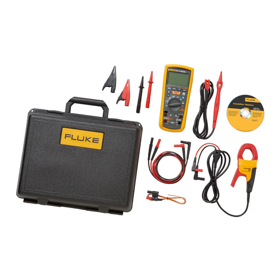
Includes the Fluke 1587 FC 2-in-1 Insulation DMM and the Fluke i400 Current Clamp
With the Fluke 1587 FC, perform insulation tests, plus a wide-range of DMM tasks with confidence and ease
Use the Fluke i400 with your Fluke 1587 FC to accurately measure AC current without breaking the circuit
The Fluke 1587 FC 2-in1 Insulation DMM
Pl/DAR measurements with TrendIt™ graphs
Memory storage through Fluke Connect Measurements app
Temperature Compensation through Fluke Connect Measurements app
VFD low-pass filter for accurate motor drive measurements
Insulation test voltages 50 V, 100 V, 250 V, 500 V, 1000 V
Insulation test voltages 500 V, 1000 V
Insulation test: 0.01 M? to 2.0 G?
Insulation test: 0.1 M? to 600 M?
Auto-discharge of capacitive voltage
Insulation test smoothing reading
Frequency / Capacitance / Diode test / Temperature
Min/Max / AC/DC Voltage / DC Millivolts / AC/DC Milliamps
Resistance (0.1 ? to 50 M?) / Continuity / Auto power off
Three-year warranty / Remote probe, test leads, alligator clips, K-type thermocouple, hard case
Fluke i400 AC Current Clamp
Advertisement
Table of Contents

Related Manuals for Fluke 1587


Summary of Contents for Fluke 1587
- Page 1 Includes the Fluke 1587 FC 2-in-1 Insulation DMM and the Fluke i400 Current Clamp With the Fluke 1587 FC, perform insulation tests, plus a wide-range of DMM tasks with confidence and ease Use the Fluke i400 with your Fluke 1587 FC to accurately measure AC current without breaking the circuit The Fluke 1587 FC 2-in1 Insulation DMM Pl/DAR measurements with TrendIt™...
- Page 2 ภาพรวมผลิ ต ภั ณ ฑ์ : Fluke 1587/i400 Current Clamp FC Kit Includes the 1587 FC 2-in-1 Insulation DMM and the i400 Current Clamp The Fluke 1587 FC Insulation Multimeter features four powerful new diagnostic functions through the Fluke Connect Measurements app: Pl/DAR timed ratio tests with TrendIt™...
- Page 3 Accuracy 60 Hz to 400 Hz ±(% of Rdg +(2% + 3), -(6% - 3) + Counts) DC Voltage Measurement Range Resolution Accuracy ±(% of Rdg + Counts) 6.000 V dc 0.001 V ±(0.09% + 2) 3 Fluke Corporation Fluke 1587/i400 Current Clamp FC Kit https://www.fluke.com/th-th/product/electrical-testing/insulation-testers/fluke-1587-i400-fc-kit...
- Page 4 300 mA, decreasing linearly to crest factor ≤1.5 at 600 mA. For non-sinusoidal waveforms add +(2% reading + 2% FS) typical, for a crest factor up to 3. ¹ 1 kHz bandwidth 4 Fluke Corporation Fluke 1587/i400 Current Clamp FC Kit https://www.fluke.com/th-th/product/electrical-testing/insulation-testers/fluke-1587-i400-fc-kit...
- Page 5 V ac Sensitivity (RMS Sine Wave)¹ 5 100.0 mV Hz to 20 kHz 600.0 mV ac V ac Sensitivity (RMS Sine Wave)¹ 20 150.0 mV kHz to 100 kHz DC Trigger Levels¹ to 20 kHz² 5 Fluke Corporation Fluke 1587/i400 Current Clamp FC Kit https://www.fluke.com/th-th/product/electrical-testing/insulation-testers/fluke-1587-i400-fc-kit...
- Page 6 50, 100, 250, 500, 1000 V Test voltage accuracy +20%, -0% Short-circuit test current 1 mA nominal Auto discharge Discharge time <0.5 second for C = 1 μF or less 6 Fluke Corporation Fluke 1587/i400 Current Clamp FC Kit https://www.fluke.com/th-th/product/electrical-testing/insulation-testers/fluke-1587-i400-fc-kit...
- Page 7 250 V (0% to +20%) Display range 60 to 250 MΩ Resolution 1 MΩ Test current 1 mA @ 250 kΩ Resistance accuracy ±(% of Rdg + ±(1.5% + 5 counts) Counts) 7 Fluke Corporation Fluke 1587/i400 Current Clamp FC Kit https://www.fluke.com/th-th/product/electrical-testing/insulation-testers/fluke-1587-i400-fc-kit...
- Page 8 0% to 40% @ 40 °C to 55 °C (104 °F to 131 °F) Vibration Random, 2 g, 5-500 Hz per MIL-PRF-28800F, Class 2 instrument Radio frequency communication 2.4 GHz ISM Band 8 Fluke Corporation Fluke 1587/i400 Current Clamp FC Kit https://www.fluke.com/th-th/product/electrical-testing/insulation-testers/fluke-1587-i400-fc-kit...
- Page 9 110% of range except for capacitance which is 100% Frequency overload protection <107 V Hz Fuse protection for mA input 0.44A, 1000 V, IR 10 kA Fluke i400 AC Current Clamp Specifications Nominal current range 400 A 9 Fluke Corporation Fluke 1587/i400 Current Clamp FC Kit https://www.fluke.com/th-th/product/electrical-testing/insulation-testers/fluke-1587-i400-fc-kit...
- Page 10 Mechanical and General Specifications Warranty 1 year Maximum conductor diameter 32 mm (1.25 in) Maximum conductor size (busbar) 750 MCM Output cable length 1.5 m (59 in) Shrouded banana plugs 10 Fluke Corporation Fluke 1587/i400 Current Clamp FC Kit https://www.fluke.com/th-th/product/electrical-testing/insulation-testers/fluke-1587-i400-fc-kit...
- Page 11 รุ ่ น FLK-1587/i400 FC Kit Fluke 1587/i400 Current Clamp FC Kit Includes: Fluke 1587 FC 2-in-1 Insulation DMM Fluke i400 Current Clamp 11 Fluke Corporation Fluke 1587/i400 Current Clamp FC Kit https://www.fluke.com/th-th/product/electrical-testing/insulation-testers/fluke-1587-i400-fc-kit...
- Page 12 การให้ บ ริ ก ารไร้ ส ายและข้ อ มู ล ผ่ า นสมาร์ ท โฟนไม่ ร วมอยู ่ ใ นการสั ่ ง ซื ้ อ พื ้ น ที ่ เ ก็ บ ข้ อ มู ล 5GB แรกให้ บ ริ ก ารฟรี . การให้ บ ริ ก ารไร้ ส ายและข้ อ มู ล ผ่ า นสมาร์ ท โฟนไม่ ร วมอยู ่ ใ นการสั ่ ง ซื ้ อ Fluke Connect อาจไม่ ม ี ใ ห้ บ ริ ก ารในบางประเทศ...
- Page 13 1587 FC/1587/1577 Insulation Multimeter Users Manual April 2005 Rev.3, 9/15 © 2005-2015 Fluke Corporation. All rights reserved. Specifications are subject to change without notice. All product names are trademarks of their respective companies.
- Page 14 LIMITED WARRANTY AND LIMITATION OF LIABILITY Each Fluke product is warranted to be free from defects in material and workmanship under normal use and service. The warranty period is three years and begins on the date of shipment. Parts, product repairs, and services are warranted for 90 days. This warranty extends only...
-
Page 15: Table Of Contents
Input Terminals ......................14 Power-Up Options ......................15 AutoHold Mode ......................16 MIN MAX AVG Recording Mode..................16 Manual Ranging and Auto Ranging ................17 AC Zero Input Behavior of True RMS Meters ..............17 VFD Low-Pass Filter (all 1587 Models) ................. 17... - Page 16 1587 FC/1587/1577 Users Manual Basic Measurements ..................... 18 AC and DC Voltage ....................19 Temperature (all 1587 Models) ................. 20 Resistance ........................ 21 Capacitance (all 1587 models) .................. 21 Continuity ........................22 Diodes (all 1587 models) ..................23 AC or DC Current ...................... 24 Insulation ........................
- Page 17 List of Tables Table Title Page Symbols ..........................4 Unpack List ........................... 5 Accessories .......................... 5 Rotary Switch Selections ...................... 7 Buttons ..........................9 Display Indicators ......................... 11 Error Messages ........................14 Input Terminal Descriptions ....................14 Power-Up Options ........................ 15 Fuse and Battery Replacement ....................
- Page 18 1587 FC/1587/1577 Users Manual...
- Page 19 Measuring Resistance ......................21 Measuring Capacitance ......................21 Testing for Continuity ......................22 Testing Diodes ........................23 Measuring AC or DC Current ....................25 Testing Insulation ........................27 Measuring Frequency ......................29 Fluke Connect™ ........................30 Testing the Fuse ........................31...
- Page 20 1587 FC/1587/1577 Users Manual...
-
Page 21: Introduction
Introduction The 1587 FC supports the Fluke Connect™ Wireless The Fluke 1587 FC, 1587, 1587T, and 1577 are System (may not be available in all regions). Fluke battery-powered, true-RMS insulation multimeters (the Connect™ is a system that wirelessly connects your Meter Product or Meter) with a 6000-count display. -
Page 22: Contacting Fluke
1587 FC/1587/1577 Users Manual Contacting Fluke Safety Information To contact Fluke, call one of the following telephone A Warning identifies conditions and procedures that are numbers: dangerous to the user. A Caution identifies conditions and procedures that can cause damage to the Product or the •... - Page 23 Insulation Multimeter Safety Information • • Keep fingers behind the finger guards on Measure a known voltage first to make the probes. sure that the Product operates correctly. • • Do not exceed the Measurement Category Use the correct terminals, function, and (CAT) rating of the lowest rated individual range for measurements.
- Page 24 1587 FC/1587/1577 Users Manual Table 1. Symbols Symbol Description Symbol Description WARNING. HAZARDOUS VOLTAGE. Risk of electric WARNING.RISK OF DANGER. shock. Consult user documentation. Battery (Low battery when shown on display.) AC (Alternating Current) Earth ...
-
Page 25: Unpack List
Table 2 is a list of accessories included with your Product. Table 3 is list of optional accessories that are available for the Product. Table 2. Unpack List Table 3. Accessories Model Accessory Accessory Part Number 1587, 1587T, 1587 FC 1577 ToolPak Magnetic go to www.fluke.com/tpak Leads TL224 TL224... -
Page 26: Hazardous Voltage
1587 FC/1587/1577 Users Manual Hazardous Voltage Battery Saver (Sleep Mode) To alert you to the presence of a potentially hazardous The Meter enters “Sleep mode” and blanks the display if voltage, when the Meter detects a voltage ≥30 V or a there is no function change or button press for 20 minutes. -
Page 27: Rotary Switch Positions
Insulation Multimeter Rotary Switch Positions Rotary Switch Positions Turn the Meter on by selecting any measurement function. The Meter presents a standard display for that function (range, measurement units, modifiers, etc.). Use the blue button to select any rotary switch alternate functions (labelled with blue letters). - Page 28 1587 FC/1587/1577 Users Manual Table 4. Rotary Switch Selections (cont.) Switch Measurement Function Position Temperature from - 40 °C to + 537 °C (- 40 °F to + 998 °F). • • • Celsius is the default temperature measurement unit. The temperature measurement you select is retained in memory when the Meter is turned off.
-
Page 29: Buttons
Insulation Multimeter Buttons Buttons Use the buttons to activate features that augment the function selected with the rotary switch. The buttons are shown and described in Table 5. Table 5. Buttons SAVE bav03f.eps Button Description Press to freeze the displayed value. Press again to release the display. When a reading changes, the display updates and the Meter beeps. - Page 30 • • When used with the Fluke Connect App on your smart device, saves a measurement to the Fluke Connect app. • Press >2 s. to turn off the radio and exit the module mode.
-
Page 31: Display
• • • Low battery. Time to replace the battery. When is on, the backlight button is disabled to conserve battery life. 1587 FC model: module mode is disabled when the battery is low. • • • •... - Page 32 Hz. “Smoothing” enabled. Smoothing dampens display fluctuations of rapidly changing inputs by • • • digital filtering. Smoothing is available for insulation testing on 1587 models only. For more on smoothing, see Power-Up Options. • • •...
- Page 33 • • • Display range in use. ManualRange 610000 Source voltage rating for insulation test: 50, 100, 250, 500 (default) or 1000 V on the 1587. 2500V • • • • 500 (default) and 1000 V ranges available on the 1577. 50 (default) and 100 V on the 1000V 1587T.
-
Page 34: Input Terminals
Invalid EEProm data. Have the Meter serviced. 1577: input terminal for voltage, continuity, resistance Invalid calibration data. Calibrate the Meter. 1587: input terminal for voltage, continuity, resistance, diode, capacitance, voltage frequency, and temperature measurements. Common (return) terminal for all measurements except ... -
Page 35: Power-Up Options
Insulation Multimeter Power-Up Options Table 9. Power-Up Options Power-Up Options Button Description Holding a button down while turning the Meter on activates a power-up option. Power-up options allow you to use (V ac and mA ac) switch position turns on all LCD segments. -
Page 36: Autohold Mode
1587 FC/1587/1577 Users Manual The Meter tracks the minimum, maximum, and average AutoHold Mode values for each display which are updated 4 times per second. Warning To prevent electrical shock, do not use the To use MIN MAX AVG recording: Display AutoHold mode to determine if a •... -
Page 37: Manual Ranging And Auto Ranging
VFD Low-Pass Filter (all 1587 Models) Note The 1587 is equipped with an ac low-pass filter to measure You cannot manually change the range in the MIN the output of variable frequency motor drives (VFD). For MAX AVG, or Display HOLD modes. -
Page 38: Basic Measurements
1587 FC/1587/1577 Users Manual Warning Basic Measurements To prevent possible electric shock or personal The figures on the following pages show how to make injury, do not use the VFD Low-Pass Filter basic measurements. function to verify the presence of hazardous When connecting the test leads to the circuit or device, voltages. -
Page 39: Ac And Dc Voltage
Insulation Multimeter Basic Measurements AC and DC Voltage Volts AC Volts DC Millivolts DC bav05f.eps Figure 2. Measuring AC and DC Voltage... -
Page 40: Temperature (All 1587 Models)
1587 FC/1587/1577 Users Manual Temperature (all 1587 Models) The Meter measures the temperature of a type-K thermocouple (included). Choose between degrees Celsius (°C) or degrees Fahrenheit (°F). 1587 FC: Press to toggle between °C or °F. °C °F 1587/1587T: Press r to toggle between °C or °F. -
Page 41: Resistance
Insulation Multimeter Basic Measurements Resistance Capacitance (all 1587 models) SAVE SAVE bav06f.eps bav07f.eps Figure 4. Measuring Resistance Figure 5. Measuring Capacitance... -
Page 42: Continuity
1587 FC/1587/1577 Users Manual Continuity The continuity test features a beeper that sounds as long as a circuit is complete. The beeper allows you to perform quick continuity tests without having to watch the display. To test for continuity, set up the Meter as shown in Figure 6. -
Page 43: Diodes (All 1587 Models)
Insulation Multimeter Basic Measurements Diodes (all 1587 models) Good Diode Good Diode Bad Diode Bad Diode HOLD MIN MAX HOLD MIN MAX TEST TEST Open Constant Beep Single Beep Shorted Forward Bias Reverse Bias bav10f.eps Figure 7. Testing Diodes... -
Page 44: Ac Or Dc Current
1587 FC/1587/1577 Users Manual Turn OFF power to the circuit under test, break circuit, AC or DC Current insert Meter in series, and turn ON power. To measure ac Warning or dc current, set up the Meter as shown in Figure 8. - Page 45 Insulation Multimeter Basic Measurements HOLD MIN MAX TEST DC Display Load Load Load bav11f.eps Figure 8. Measuring AC or DC Current...
-
Page 46: Insulation
1587 FC/1587/1577 Users Manual 5. Push and hold to start the test. The secondary Insulation display shows the test voltage applied to the circuit Insulation tests should only be performed on dead circuits. under test. The high voltage symbol (Z) along with a Check the fuse before testing. - Page 47 Insulation Multimeter Basic Measurements PI/DAR Polarization Index (PI) is the ratio of the 10-minute insulation resistance to the 1 minute insulation resistance. Dielectric Absorption Ratio (DAR) is the ratio of the 1-minute insulation resistance to the 30 second insulation resistance. Insulation tests should only be performed on de-energized circuits.
-
Page 48: Frequency (All 1587 Models)
1587 FC/1587/1577 Users Manual 5. Press and release to start the test. The secondary Frequency (all 1587 Models) display shows the test voltage applied to the circuit The Meter measures the frequency of a voltage or current under test. The high voltage symbol (Z) along with the signal by counting the number of times the signal crosses primary display show the resistance in MΩ... - Page 49 Insulation Multimeter Basic Measurements AC/DC Voltage Frequency AC/DC Current Frequency Load bav12f.eps Figure 10. Measuring Frequency...
-
Page 50: Fluke Connect™ Wireless System
3. On your smartphone, go to Settings > Bluetooth. A3001 T3000 Turn on the Bluetooth function. 4. Go to the Fluke Connect App and select your Meter from the list that shows in the app. bav17.eps You are now able to take, save, and share measurements. -
Page 51: How To Clean
Insulation Multimeter How to Clean How to Clean Periodically wipe the case with a damp cloth and mild detergent. Do not use abrasives or solvents. Dirt or moisture in the terminals can affect readings. Battery Test To test the batteries, press and turn to the rotary switch to the position. -
Page 52: Battery And Fuse Replacement
1587 FC/1587/1577 Users Manual 3. Remove and replace the batteries. Battery and Fuse Replacement 4. Replace the battery door and secure by turning the Replace the fuse and batteries as shown in Table 10. battery door lock until the lock symbol aligns with the Follow the steps below to replace the batteries. -
Page 53: General Specifications
Insulation Multimeter General Specifications General Specifications Maximum Voltage Applied to any Terminal and Common ........1000 V Fuse Protection for mA input ........0.44 A, 1000 V, IR 10 kA Batteries ..............Four AA batteries (NEDA 15A or IEC LR6) Battery Life .............. - Page 54 1587 FC/1587/1577 Users Manual Wireless Radio with Adapter Frequency Range ........... 2402 MHz to 2480 MHz Output Power ..........<10 mW Radio Frequency Certification ......FCC: T68-FBLE, IC: 6627A-FBLE Electromagnetic Compatibility International ............ IEC 61326-1:Portable Electromagnetic Environment; IEC 61326-2-2 CISPR 11: Group 1, Class A Group 1: Equipment has intentionally generated and/or uses conductively-coupled radio frequency energy that is necessary for the internal function of the equipment itself.
-
Page 55: Electrical Specifications
±(2 % + 3) 1000 V ±(2 % + 3) ±(2 % + 3) 1 kHz bandwidth. Low-Pass Filter Voltage (all 1587 models) 50 Hz to 60 Hz 60 Hz to 400 Hz Range Resolution ±(% of Rdg + Counts) ±(% of Rdg + Counts) - Page 56 Input Impedance ..........10 MΩ (nominal), <100 pF, ac-coupled Common Mode Rejection Ratio (1 kΩ unbalanced) ..........>60 dB at dc, 50 or 60 Hz DC Voltage Measurement Accuracy 1587 and 1587T Accuracy 1577 Range Resolution ±(% of Rdg + Counts) ±(% of Rdg + Counts)
- Page 57 Insulation Multimeter Electrical Specifications DC Millivolts Measurement Accuracy all 1587 models Accuracy 1577 Range Resolution ±(% of Rdg + Counts) ±(% of Rdg + Counts) 600.0 mV dc 0.1 mV ±(0.1 % + 1) ±(0.2 % + 1) DC and AC Current Measurement...
- Page 58 Open Circuit Test Voltage ........<8.0 V dc Short Circuit Current ........... <1.1 mA Diode Test (all 1587 models) Diode Test Indication .......... Display voltage drop: 0.6 V at 1.0 mA nominal test current: Accuracy ............. ±(2 % + 3) Continuity Test Continuity Indication ...........
- Page 59 Insulation Multimeter Electrical Specifications Frequency Counter Sensitivity (all 1587 models) V ac Sensitivity (RMS Sine Wave) Input Range DC Trigger Levels to 20 kHz 5 Hz to 20 kHz 20 kHz to 100 kHz 600.0 mV ac 100.0 mV 150.0 mV 6.0 V...
- Page 60 Model 1577 ..........0.1 MΩ to 600 MΩ Model 1587T ..........0.01 MΩ to 100 MΩ Test Voltages Model 1587, 1587 FC ......... 50, 100, 250, 500, 1000 V Model 1577 ..........500, 1000 V Model 1587T ..........50, 100 V Test Voltage Accuracy ........
- Page 61 Insulation Multimeter Electrical Specifications Model 1587/1587 FC Resistance Accuracy Output Voltage Display Range Resolution Test Current ±(% of Rdg + Counts) 0.01 to 6.00 MΩ 0.01 MΩ 50 V ±(3 % + 5 counts) 1 mA @ 50 kΩ (0 % to +20 %) 6.0 to 50.0 MΩ...
- Page 62 1587 FC/1587/1577 Users Manual Model 1587T Resistance Accuracy Output Voltage Display Range Resolution Test Current ±(% of Rdg + Counts) 0.01 to 6.00 MΩ 0.01 MΩ 50 V ±(3 % + 5 counts) 1 mA @ 50 kΩ (0 % to +20 %) 6.0 to 50.0 MΩ...
Need help?
Do you have a question about the 1587 and is the answer not in the manual?
Questions and answers