Fluke 125 Getting Started
Industrial scopemeter
Hide thumbs
Also See for 125:
- User manual (128 pages) ,
- Specifications (2 pages) ,
- Service manual (96 pages)

Related Manuals for Fluke 125


Summary of Contents for Fluke 125
- Page 1 ® Fluke 125 Industrial ScopeMeter Getting Started Dec 2006 © 2006 Fluke Corporation, All rights reserved. Printed in The Netherlands All product names are trademarks of their respective companies.
- Page 2 Contents of the Fluke 125 Test Tool Kit (2x) (2x) (3x) Figure 1. Fluke 125 Test Tool Kit...
-
Page 3: Getting Started
Safety Information: Read First This Getting Started Manual provides basic information The Fluke 125 ScopeMeter Test Tool (hereafter referred on the Fluke 125 ScopeMeter Test Tool. For complete to as “Test Tool”) complies with: operating instructions, refer to the Users Manual on the •... - Page 4 • Before use check that the selected/indicated and adapters supplied with the Test Tool, or voltage range on the PM8907 matches the indicated as suitable for the Fluke 125 Test local line power voltage and frequency. Tool. • For the PM8907/808 universal Battery •...
-
Page 5: Preparing For Use
Getting Started Preparing for Use Whenever it is likely that safety has been impaired, the Max. Input Voltages Test Tool must be turned off and disconnected from the Input A and B directly ....... 600 V CAT III line power. The matter should then be referred to qualified Input A and B via BB120 ...... -
Page 6: Powering/Resetting The Test Tool
Fluke 125 Getting Started Powering/Resetting the Test Tool Dim / Brighten the backlight. Turning power on/off: Press CONTRAST. The Test Tool powers up in its last Adjust the Contrast of the display. setup configuration. Resetting the Test Tool to the factory (default) settings:... -
Page 7: Making Menu Selections
Getting Started Making Menu Selections Menu area (C): Displays the menu that provides choices Making Menu Selections available through the blue arrow keys and the ENTER key: Selection of a function in the menu is done as follows: A menu pops up after operation of, for instance, the MENU key. - Page 8 Fluke 125 Getting Started Input Connections and Grounding For Voltage measurements use the Shielded Test Leads on Input A (red) and/or Input B (grey). For Current measurements use a current probe on Input A and/or Input B. For Power measurements use a voltage probe on Input A and a current probe on Input B.
-
Page 9: Displaying An Unknown Signal With Connect-And-View™ (Auto Set)
Getting Started Displaying an Unknown Signal with Connect-and-View™ (Auto Set) Displaying an Unknown Signal with Freezing the Screen Connect-and-View™ (Auto Set) You can freeze the screen (Waveforms and Readings) with the HOLD/RUN key. This allows you read the screen The Connect-and-View™ function enables hands-off while the Test Tool has been disconnected from the operation to display complex unknown signals in Device to be checked. - Page 10 Fluke 125 Getting Started Scope Measurements on Input A and B Open the PEAK Submenu. Choose ac voltage (Vac) measurement for Input A: Highlight PEAK-PEAK. Open the A MEASUREMENTS menu. Press ENTER to confirm the selection. Highlight Vac. Now you will see a screen like in Figure 5. The A and B traces give a graphical representation of the waveforms applied to Input A and Input B.
- Page 11 Getting Started Scope/Meter Measurements Changing the Waveform Representation Enables the arrow keys for Trigger Level and Slope. Changing the amplitude: Adjust the Trigger Level. Enlarge or reduce the waveform amplitude; there are separate keys for Input A and Select Negative / Positive Slope. Input B.
- Page 12 Select the cursor to be moved. Use the of 10:1 voltage probes other than the blue arrow keys to move the cursors probe supplied with Fluke 125. This is Depending on cursor measurement type: necessary for correct high frequency measurements.
- Page 13 Getting Started Scope/Meter Measurements Trigger Options Waveform/Reading Smooth Options Open the application mode menu. Open the application mode menu. Open the TRIGGER menu: Open the SMOOTH menu: INPUT: WAVEFORM: • A, B: Triggering on the input A or input B •...
-
Page 14: Harmonics Measurements
Fluke 125 Getting Started Harmonics Measurements The harmonics screen F1…F4 key functions are: Use a voltage probe on Input A and a current probe on Show the voltage (VOLT) harmonics, the Input B. current (AMP) harmonics, or the power (WATT) harmonics. -
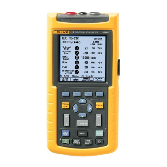
Page 15: Fieldbus Measurements
Getting Started Fieldbus Measurements Bus Health Screen Fieldbus Measurements The following icons are used to indicate the bus Connect the bus to Input A, and depending on the bus measurement status: type also to input B. Selecting the Fieldbus Mode and Bus Type bus activity indicators. - Page 16 Fluke 125 Getting Started Bus Health Screen Softkey Functions Setting up the Limits The bus health screen shows a softkey button bar like the To set up the test limits of the current bus type, do the one shown below: following: Select the SETUP LIMITS…...
-
Page 17: Plotting Measurements Over Time (Trendplot )
Getting Started Plotting Measurements over Time (TrendplotTM) Trendplot Screen Softkey Functions Plotting Measurements over Time (Trendplot Stop the Trendplot. The TrendPlot™ function plots a graph derived from the TREND RESTART: Start a new Trendplot. MAIN (large) readings in the SCOPE/METER mode or in the HARMONICS mode as a function of time. -
Page 18: User Options Menu
Fluke 125 Getting Started User Options Menu SAVE / PRINT Functions • USER OPTIONS gives submenus to Show the PRINT SCREEN, RECALL configure the Test Tool to your personal DELETE… and SAVE… key labels. taste. • The function keys F1, F2, and F3 give PRINT SCREEN: The active screen is printed.
Need help?
Do you have a question about the 125 and is the answer not in the manual?
Questions and answers