Table of Contents
Advertisement
Available languages
Available languages
Quick Links
To prevent possible SERIOUS INJURY or DEATH from a closing
gate or door:
• Entrapment protection devices MUST be installed per the
operator owner's manual.
• Be sure to DISCONNECT POWER to the operator BEFORE
installing the photoelectric sensor.
• The gate or door MUST be in the fully opened or closed
position BEFORE installing the LiftMaster Monitored
Entrapment Protection device.
APPLICATION
NOTE: The images throughout this manual are for reference and your product may look different.
The CPS-U and CPS-UN4 are suitable for use with LiftMaster Commercial Door Operators (Medium Duty Logic, Logic 3 or 4, models
FDC, FDCL, FDO, and LGE). The CPS-UN4 may also be used with gate operator (Series models: CSL24V, CSW24V, RSW12V, RSL12V,
LA400, LA412, and LA500). The CPS-UN4 is suitable for use in applications where the photoelectric sensors will be exposed to moisture.
These photoelectric sensors are LiftMaster Monitored Entrapment Protection (LMEP) devices.
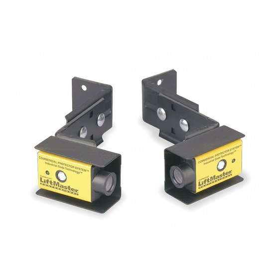
THE PROTECTOR SYSTEM
IMPORTANT INFORMATION ABOUT THE PHOTOELECTRIC SENSOR
Be sure power to the operator is disconnected.
When properly connected and aligned, the photoelectric sensor will detect an obstruction in the path of its invisible light beam. If an
obstruction breaks the light beam while the door/gate is closing, the operator will stop and typically reverse to the full open position.
The sensors must be installed so that the sending and receiving sensors face each other across the entrapment zone, no more than
6" (15 cm) above the fl oor for a garage door and no more than 27.5" (69.8 cm) above grade for a gate. Either can be installed on the left
or right of the entrapment zone as long as the sun never shines directly into the receiving eye lens.
The brackets must be securely fastened to a solid surface such as the wall framing. If installing in masonry construction, add a piece of
wood at each location to avoid drilling extra holes in masonry if repositioning is necessary.
The invisible light beam path must be unobstructed. No part of the gate or garage door (or door tracks, springs, hinges, rollers or other
hardware) may interrupt the beam while the door/gate is closing. If it does, use a piece of wood to build out each sensor mounting
location to the minimum depth required for light beam clearance.
GARAGE DOOR
Entrapment Zone
Photoelectric
Invisible Light Beam
Sensor
Protection Area
6" (15 cm)
Facing the door from inside the garage (installation
procedures are the same for all door types).
®
SWING GATE
Photoelectric
Sensors
Photoelectric
Sensor
6" (15 cm)
27.5"
(69.8 cm)
Invisible Light Beam
max.
COMMERCIAL PROTECTOR SYSTEM
• Correctly connect and align the photoelectric sensor.
• Install the photoelectric sensor beam NO HIGHER than 6"
(15 cm) above the fl oor for door and 27.5" (69.8 cm) above
grade for gate operators.
Invisible Light Beam
Protection Area
Photoelectric
Sensors
Protection Area
1
MODELS CPS-U AND CPS-UN4
SLIDE GATE
Photoelectric Sensor
Invisible Light Beam
Protection Area
®
Photoelectric
Sensor
!
27.5"
(69.8 cm)
max.
Advertisement
Table of Contents

Subscribe to Our Youtube Channel
Related Manuals for Chamberlain CPS-U


Summary of Contents for Chamberlain CPS-U
- Page 1 NOTE: The images throughout this manual are for reference and your product may look different. The CPS-U and CPS-UN4 are suitable for use with LiftMaster Commercial Door Operators (Medium Duty Logic, Logic 3 or 4, models FDC, FDCL, FDO, and LGE). The CPS-UN4 may also be used with gate operator (Series models: CSL24V, CSW24V, RSW12V, RSL12V, LA400, LA412, and LA500).
- Page 2 INSTALL MODEL CPS-U ASSEMBLE AND MOUNT THE BRACKETS The following instructions show recommended assembly of the bracket(s) and “C” wrap based on the wall installation of the photoelectric sensors on each side of the door or on the door Mounting Bracket with Square Holes tracks themselves.
- Page 3 INSTALL MODEL CPS-U MOUNT AND WIRE THE PHOTOELECTRIC Wing Nut SENSORS “C” Wrap Sensor Wire Be sure power to the operator is disconnected. 1. Center each sensor in the bracket with the lenses pointing Indicator Light toward each other across the door.
- Page 4 INSTALL MODEL CPS-UN4 GARAGE DOOR ASSEMBLE AND MOUNT THE BRACKETS Make sure the brackets are aligned so the photoelectric sensors Photoelectric Photoelectric Sensor Sensor will face each other across the entrapment zone. 6" 6" FOR DOORS (15 cm) (15 cm) Mount sensors no more than 6"...
-
Page 5: Conduit Connections
INSTALL MODEL CPS-UN4 CONDUIT CONNECTIONS Be sure power to the operator is disconnected. 1. Use a liquid tight fi tting (1/2" trade size) with sealing washer to connect to sensors. The sensors are provided with 36" long leads. We recommend the use of a liquid tight junction box near each sensor to make the connection to the sensor leads. Use rigid or fl exible liquid tight conduit (depending on local codes) from junction boxes to operator. -
Page 6: Wiring Connections
WIRING CONNECTIONS COMMERCIAL DOOR OPERATORS Control Board MEDIUM DUTY LOGIC White (Blue) White/Black (Brown) LOGIC 3 OR 4 Control Board 24VAC POWER 24VAC TIMER DEFEAT White (Blue) COMMON White/Black (Brown) LMEP: TIMER EDGE: ENABLE OPEN CLOSE STOP MODELS FDC, FDCL, FDO, AND LGE 13 14 15 16 17 18 19 20 21 22 23 24 1 2 3 4 5 6 7 8 9 10 11 12 Control Board... - Page 7 WIRING CONNECTIONS GATE OPERATORS MODELS CSL24V AND CSW24V SERIES Sensor for CLOSE cycle. See gate manual for placement of sensors. Sensor for OPEN cycle. See gate manual for placement of sensors. Control Board MODELS LA412, RSW12V, AND RSL12V SERIES Sensor for OPEN cycle. See gate manual for placement of sensors.
-
Page 8: Test The Protector System
SIMPLY DIAL OUR TOLL FREE NUMBER: 1-800-528-2806 www.liftmaster.com WHEN ORDERING REPAIR PARTS, ALWAYS GIVE THE FOLLOWING INFORMATION: • PART NUMBER • PART NAME • MODEL NUMBER ADDRESS ORDERS TO: THE CHAMBERLAIN GROUP, INC. Technical Support Group 6050 S. Country Club Road Tucson, Arizona 85706... - Page 9 : Les illustrations de ce manuel ne sont fournies qu’à titre de référence; votre produit peut avoir une apparence différente. Les modèles CPS-U et CPS-UN4 conviennent à l’utilisation des actionneurs de porte commerciaux LiftMaster (Logique de gamme intermédiaire, Logique 3 ou 4, modèles FDC, FDCL, FDO, and LGE). Le modèle CPS-UN4 peut aussi être utilisé avec l’actionneur de portail (modèles de AVERTISSEMENT série : CSL24V, CSW24V, RSW12V, RSL12V, LA400, LA412 et LA500).
- Page 10 INSTALLATION DU MODÈLE CPS-U ASSEMBLER ET MONTER LES SUPPORTS Les instructions suivantes montrent l'assemblage recommandé de support(s) et de supports en C selon l'installation murale des capteurs photoélectriques de chaque côté de la porte ou sur les rails de porte eux- Support de montage mêmes.
- Page 11 INSTALLATION DU MODÈLE CPS-U MONTER ET CÂBLER LES CAPTEURS Écrou à oreilles Support PHOTOÉLECTRIQUES Fil du capteur en C Vérifi er que l’alimentation électrique de l’actionneur est débranchée. 1. Centrer chaque capteur dans le support, les lentilles pointant l'une vers Lampe-témoin...
- Page 12 INSTALLATION DU MODÈLE CPS-UN4 PORTE DE GARAGE ASSEMBLER ET MONTER LES SUPPORTS S’assurer que les supports sont alignés de sorte que les capteurs Capteur Capteur photoélectrique photoélectrique photoélectriques se fassent face de chaque côté de la zone de piégeage. POUR LES PORTES 15 cm 15 cm (6 po)
- Page 13 INSTALLATION DU MODÈLE CPS-UN4 CONNEXIONS DES CONDUITES Vérifi er que l’alimentation électrique de l’actionneur est débranchée. 1. Se servir d’un raccord étanche aux liquides (commercial de ½ po) avec une rondelle d’étanchéité pour connecter les capteurs. Les capteurs sont fournis avec des fi ls d’alimentation de 91 cm (36 po) de long. Nous recommandons l’utilisation d’une boîte de connexion étanche aux liquides à proximité...
- Page 14 CONNEXIONS DE CÂBLAGE ACTIONNEURS DE PORTE COMMERCIAUX Tableau de commande LOGIQUE DE GAMME INTERMÉDIAIRE Blanc (Bleu) Blanc/noir (Brun) LOGIQUE 3 OU 4 Tableau de commande 24VAC POWER 24VAC TIMER DEFEAT Blanc (Bleu) COMMON Blanc/noir (Brun) LMEP: TIMER EDGE: ENABLE OPEN CLOSE STOP MODÈLES FDC, FDCL, FDO ET LGE...
- Page 15 CONNEXIONS DE CÂBLAGE ACTIONNEURS DE PORTAIL MODÈLES DE SÉRIES CSL24V ET CSW24V Capteur pour cycle FERMÉ. Consulter le manuel du portail pour le placement des capteurs. Capteur pour cycle OUVERT. Consulter le manuel du portail pour le placement des capteurs. Tableau de commande MODÈLES DE SÉRIES LA412, RSW12V ET RSL12V Capteur pour cycle OUVERT.
-
Page 16: Dépannage
NOM DE LA PIÈCE • NUMÉRO DE MODÈLE PASSER VOS COMMANDES À : THE CHAMBERLAIN GROUP, INC. Technical Support Group 6050 S. Country Club Road Tucson, Arizona 85706 © 2012, The Chamberlain Group, Inc. All Rights Reserved 01-35688D Tous droits réservés...
Need help?
Do you have a question about the CPS-U and is the answer not in the manual?
Questions and answers