Table of Contents
Advertisement
Available languages
Available languages
Quick Links
INTRODUCTION
APPLICATION
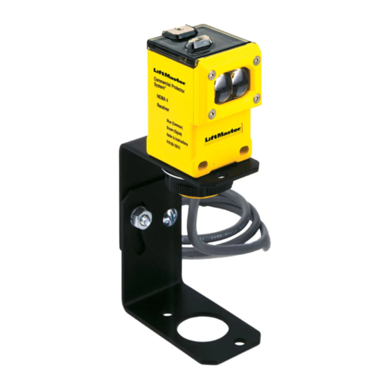
NOTE: The images throughout this manual are for reference and
your product may look different.
The Commercial Protector System is suitable for use in
applications where the photoelectric sensors will be exposed to
moisture. The CPS-UN4 and CPSUN4G are LiftMaster Monitored
Entrapment Protection (LMEP) devices and are compatible with
the following operators:
LiftMaster
Models FDC, FDCL, FDO, and LGE, Medium
Commercial Door
Duty Logic, Logic 3, Logic 4, and Logic 5
Operators
LiftMaster Legacy
Models CSL24V, CSW24V, RSL12V,
Gate Operators
RSW12V, LA400, LA412 and LA500
LiftMaster 2016
Models HCTDCU, LA400PKGU, LA412PKGU,
UL 325 Gate
LA500PKGU, CSL24U, CSW24U, RSL12U,
Operators
RSW12U, CSW200501U, CSW200101U,
SL3000501U, SL3000101U, SL585U family,
and SL595U family
IMPORTANT INFORMATION ABOUT THE
PHOTOELECTRIC SENSOR
Be sure power to the operator is disconnected.
When properly connected and aligned, the photoelectric sensor
will detect an obstruction in the path of its invisible light beam.
If an obstruction breaks the light beam while the door/gate is
closing, the operator will stop and typically reverse to the full open
position.
The sensors must be installed so that the emitter and receiver
sensors face each other across the entrapment zone and the beam
is no more than 6" (15 cm) above the fl oor for a commercial door
and no more than 27.5" (69.8 cm) above grade for a gate for
entrapment protection. Either can be installed on the left or right of
the entrapment zone as long as the sun never shines directly into
the receiver eye lens.
The brackets must be securely fastened to a solid surface such as
the wall framing. If installing in masonry construction, add a piece
of wood at each location to avoid drilling extra holes in masonry if
repositioning is necessary.
The invisible light beam path must be unobstructed. No part of
the gate or door (or door tracks, springs, hinges, rollers or other
hardware) may interrupt the beam while the door/gate is closing.
If it does, use a piece of wood to build out each sensor mounting
location to the minimum depth required for light beam clearance.
For commercial doors, additional photoelectric sensors may
be added at heights greater than 6" (15 cm) above the fl oor for
vehicle/property detection.
COMMERCIAL PROTECTOR SYSTEM
MODELS CPS-UN4 AND CPSUN4G
To prevent possible SERIOUS INJURY or DEATH from a closing
gate or door:
• Entrapment protection devices MUST be installed per the
operator owner's manual for each entrapment zone.
• Be sure to DISCONNECT POWER to the operator BEFORE
installing the photoelectric sensor.
• The gate or door MUST be in the fully opened or closed
position BEFORE installing the LiftMaster Monitored
Entrapment Protection device.
• Correctly connect and align the photoelectric sensor.
• For entrapment protection, install the photoelectric sensor
BEAM NO HIGHER than 6" (15 cm) above the fl oor for door
and 27.5" (69.8 cm) above grade for gate operators.
WARNING: This product can expose you to chemicals including
lead, which are known to the State of California to cause cancer
or birth defects or other reproductive harm. For more information
go to www.P65Warnings.ca.gov
Photoelectric
Sensor
Vehicle/Property Detection
Photoelectric
Sensor
6" (15 cm)
Monitored Entrapment Protection
Facing the door from inside the garage
(installation procedures are the same for all door types).
Photoelectric
Sensors
Invisible Light Beam
Protection Area
27.5"
(69.8 cm)
max.
Photoelectric Sensor
Invisible Light Beam
Protection Area
1
DOOR
Invisible Light Beam
Protection Area
Entrapment Zone
SWING GATE
Invisible Light Beam
Protection Area
Photoelectric
SLIDE GATE
Photoelectric
Sensor
®
Photoelectric
Sensor
Photoelectric
Sensor
6" (15 cm)
Sensors
27.5"
(69.8 cm)
max.
Advertisement
Table of Contents

Related Manuals for Chamberlain CPS-UN4


Summary of Contents for Chamberlain CPS-UN4
- Page 1 • Be sure to DISCONNECT POWER to the operator BEFORE moisture. The CPS-UN4 and CPSUN4G are LiftMaster Monitored installing the photoelectric sensor. Entrapment Protection (LMEP) devices and are compatible with •...
-
Page 2: Installation
INSTALLATION ASSEMBLE AND MOUNT THE BRACKETS Make sure the brackets are aligned so the photoelectric sensors will face each other across the entrapment zone. The brackets can be mounted on the ground, door track, or wall. GATE DOOR Mount sensors no more than 6" (15 cm) above the fl oor and at a Mount within 5"... -
Page 3: Conduit Connections
INSTALLATION CONDUIT CONNECTIONS 1. Disconnect power to the operator. 2. Use a liquid tight fi tting (1/2" [1.3 cm] trade size) with sealing washer to connect to sensors. The sensors are provided with 36" (91.4 cm) long leads. LiftMaster recommends the use of a liquid tight junction box near each sensor to make the connection to the sensor leads. -
Page 4: Commercial Door Operators
INSTALLATION Recommended installation for adjacent doors and more than one set of photoelectric sensors. For LOGIC 4 and LOGIC 5 Operators, a CPS3CARD is required to wire a second set of monitored photoelectric sensors. DOOR #1 DOOR #2 DOOR #3 Vehicle/Property Detection Vehicle/Property Detection Vehicle/Property Detection... - Page 5 WIRING The photoelectric sensors can be wired to function for either the open or close cycle depending on where they are wired on the control board. Refer to your gate operator manual for more information. LEGACY GATE OPERATORS MODEL LA500 MODELS CSL24V AND CSW24V CONTROL BOARD CONTROL BOARD...
-
Page 6: Troubleshooting
TEST 1. Connect power to the operator. 2. Align the photoelectric sensors so the green LED on the emitter sensor and the yellow LED on the receiver sensor glow steadily. 3. Press the OPEN button to fully open the door/gate. 4. - Page 7 à cellule photoélectrique seront exposés propriétaire pour chaque zone de piégeage. à l’humidité. Les modèles CPS-UN4 et CPSUN4G sont des dispositifs • S’assurer de DÉBRANCHER L’ALIMENTATION à l’actionneur surveillés de protection contre le piégeage LiftMaster compatibles AVANT l’installation du capteur photoélectrique.
- Page 8 INSTALLATION ASSEMBLER ET MONTER LES SUPPORTS S’assurer que les supports sont alignés de sorte que les capteurs photoélectriques se fassent face de chaque côté de la zone de piégeage. Les supports peuvent être montés sur le sol, les guides de porte ou au mur. PORTAIL PORTE Monter les capteurs à...
- Page 9 INSTALLATION CONNEXIONS DES CONDUITES 1. Déconnecter l’alimentation de l’actionneur. 2. Se servir d’un raccord étanche aux liquides (commercial de 1.3 cm [1/2 po]) avec une rondelle d’étanchéité pour connecter les capteurs. Les capteurs sont fournis avec des fi ls d’alimentation de 91,4 cm (36 po) de long. Nous recommandons l’utilisation d’une boîte de connexion étanche aux liquides à...
- Page 10 INSTALLATION Pour les actionneurs LOGIC 4 et Installation recommandée pour des portes adjacentes et plus d’un jeu de capteurs photoélectriques. LOGIC 5, une CARTE CPS3 est exigée pour câbler un deuxième ensemble de capteurs à cellule photoélectrique. PORTE NO 1 PORTE NO 2 PORTE NO 3 Détection de véhicules/de la propriété...
- Page 11 CÂBLAGE Les capteurs à cellule photoélectrique peuvent être câblés de manière à fonctionner pour le cycle d’ouverture ou de fermeture, selon l’endroit où ils sont câblés sur le tableau de commande. Consulter le manuel d’installation de votre actionneur de barrière pour plus d’information.
-
Page 12: Dépannage
ESSAI 1. Connecter l’alimentation à l’actionneur. 2. Aligner les capteurs à cellule photoélectrique de manière à ce que la DEL verte sur le capteur de l’émetteur et la DEL jaune sur le capteur du récepteur s’allument en continu. 3. Appuyer sur le bouton OUVRIR pour ouvrir complètement la porte/le portail. 4.
Need help?
Do you have a question about the CPS-UN4 and is the answer not in the manual?
Questions and answers