Advertisement
Quick Links
EPCC-BS
Electric cylinder
Operating instructions
8152505
2021-04b
[8152507]
Translation of the original instructions
© 2021 all rights reserved to Festo SE & Co. KG
1
Applicable Documents
All available documents for the product è www.festo.com/sp.
2
Safety
2.1
Safety instructions
– Observe labelling on the product.
– Prior to assembly, installation and maintenance work: Switch off power supply,
ensure that it is off and secure it against being switched back on.
– Store the product in a cool, dry, UV-protected and corrosion-protected environ-
ment. Ensure that storage times are kept to a minimum.
– Observe tightening torques. Unless otherwise specified, the tolerance
is ± 20 %.
2.2
Intended Use
The electric cylinder is intended to be used for positioning payloads in combina-
tion with tools or as a drive when external guides are used.
2.3
Training of qualified personnel
Work on the product may only be carried out by qualified personnel who can
evaluate the work and detect dangers. The qualified personnel have knowledge
and experience in handling electric drives and axes.
3
Additional information
– Contact the regional Festo contact if you have technical problems
è www.festo.com.
– Accessories è www.festo.com/catalogue.
4
Product overview
4.1
Function
The electric cylinder converts the rotary motion of the mounted motor into a linear
motion of the non-rotating piston rod. The lead screw converts the torque of the
motor into a feed force. The linear movement of the piston rod is guided by the
guide in the guide ring. Sensors enable the monitoring of end positions, reference
position and intermediate position.
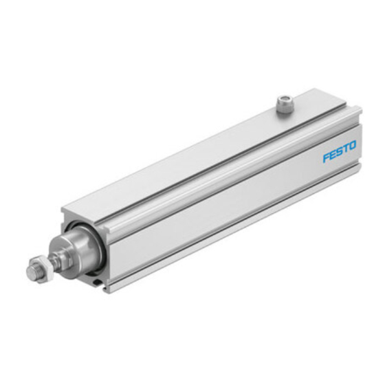
4.2
Product design
1
2
3
4
5
6
Fig. 1: Product design EPCC-BS
Festo SE & Co. KG
Ruiter Straße 82
73734 Esslingen
Deutschland
+49 711 347-0
www.festo.com
7
1
Piston rod
2
Threaded hole for mounting
Guide ring
3
4
Cylinder profile
8
Sealing air connection with filter
5
element
9
Interface for motor mounting kit
6
7
Drive hub
10
Slot for sensor bracket
8
9
Slot for profile mounting
10
Slot for slot nut
5
Transport and storage
NOTICE
Unexpected and unbraked movement of components
• Secure moving components for transport.
Transport and Storage Conditions
– Take product weight into account è Technical data.
– Take the product focus into consideration.
– Store and transport the product in its original packaging.
– Store product in a cool, dry, shaded and corrosion protected environment.
– Store product in ambient conditions without oils, greases and degreasing
vapours.
– Ensure short storage times.
6
Assembly
6.1
Safety
WARNING
Risk of Injury due to Unexpected Movement of Components
For vertical or slanted mounting position: when power is off, moving parts can
travel or fall uncontrolled into the lower end position.
• Bring moving parts of the product into a safe end position or secure them
against falling.
6.2
Unpacking
1. Open packaging.
2. Remove all transport materials (e.g. foils, caps, cardboard boxes).
3. Remove the product from the packaging and place it on the mounting surface.
4. Dispose of packaging and transport materials.
6.3
Mounting the motor
Transverse load on the drive hub
When mounting the motor and motor mounting kit, do not exceed the maximum
transverse load F
of the drive hub (e.g. toothed belt tension when mounting the
R
parallel kit) è 12.1 Technical data, mechanical.
Axial kit EAMM-A
Tab. 1: Overview of motor mountings
Requirement
– Only loosen screws or threaded pins that are described in the directions in the
instruction manuals.
– Sufficient space for reaching and securing the sealing air connection è 6.6
Mounting accessories.
1. Select the motor and motor mounting kit from
Festoè www.festo.com/catalogue.
If other motors are used: observe the critical limits for forces, torques and
velocities.
2. Fasten motor mounting kit, observe instruction manual è www.festo.com/sp.
3. Fasten the motor without tension. Support large and heavy motors.
Connect motor cables only on completion of mounting.
6.4
Mounting the cylinder
High mechanical loads on the mounting connections
If high parallel torques are applied to the drive system at the same time, this leads
to high mechanical loads at the mounting interfaces.
• If the mounting position is inclined or horizontal mounting position with direct
mounting, the drive system requires additional support near the motor
mounting.
Requirement
– No collision with mounting and sensor components in the movement space of
the attachment component.
– Sufficient space to reach maintenance interfaces.
– Sufficient space for reaching and securing the sealing air connection.
– Flat mounting surface maximum 0.2 mm over the stroke length of the bearing
surface.
– No distortion or bending when installing the product.
1. Select mounting attachments è www.festo.com/catalogue.
2. Place the mounting attachments on the support points.
3. Tighten retaining screws.
Observe the maximum tightening torque and screw-in depth.
For additional information, contact your local Festo Service.
Parallel kit EAMM-U
Advertisement

Related Manuals for Festo EPCC-BS-25


Summary of Contents for Festo EPCC-BS-25
- Page 1 • Bring moving parts of the product into a safe end position or secure them against falling. Translation of the original instructions Unpacking © 2021 all rights reserved to Festo SE & Co. KG 1. Open packaging. 2. Remove all transport materials (e.g. foils, caps, cardboard boxes). Applicable Documents 3.
- Page 2 Profile mounting EAHF-L2 – Avoidance of hard impacts at the end positions. Swivel mounting EAHS – Prevention of contamination in the slots. Swivel flange SNC... 1. Select accessories è www.festo.com/catalogue. è Screw Instruction manual www.festo.com/sp 2. Mount the sensor (reference or query): Tab.
-
Page 3: Operation
= mass moment of inertia per kg payload Block-shaped acceleration profiles (without jerk limitation) can have the following è Additional information www.festo.com/catalogue effects: Tab. 11: Speed and energy at the end positions • High mechanical loads on the lead screw due to high force peaks. - Page 4 Risk of injury due to unexpected movement of components. • Protect the positioning range from unwanted intervention. Use the Festo sizing software for sizing the driveè www.festo.com/sp. • Keep foreign objects out of the positioning range. Additional information è www.festo.com/catalogue.
- Page 5 Tab. 16: Materials and weight 12.2 Characteristic curves Additional information è www.festo.com/catalogue. Transverse load of piston rod EPCC-BS Maximum transverse load Fy, Fz on the piston rod as a function of the piston rod length l Fig. 3: Maximum lateral force Fy, Fz and piston rod length l Fig.
Need help?
Do you have a question about the EPCC-BS-25 and is the answer not in the manual?
Questions and answers