Advertisement
Quick Links
ERMS
Rotary drive unit
Operating instructions
8174351
2022-04c
[8174353]
Translation of the original instructions
© 2022 all rights reserved to Festo SE & Co. KG
IO-Link® is a registered trademark of its respective trademark holder in certain
countries.
1
About this document
1.1
Applicable documents
All available documents for the product è www.festo.com/sp.
Type
Product
EMCS-ST
Integrated drive
NEFC-M12G8-0.3-M12G5-LK
Adapter
Tab. 1: Applicable documents for the product
1.2
Product version
This documentation refers to the following datasets:
– Firmware version of the integrated drive from "v19.0.4.107_release"
– IO-Link device description file (IODD) from V1.2.6
– Adapter NEFC from production date 01/2022
When using a different firmware version, check whether a corresponding version
of the documentation is available è www.festo.com/sp.
2
Safety
2.1
Safety instructions
– Observe labelling on the product.
– Before working on the product, switch off the power supply and secure it
against being switched on again.
– Store the product in a cool, dry environment protected from UV and corrosion.
Keep storage times short.
– Observe the tightening torques. Unless otherwise specified, the tolerance is
± 20%.
2.2
Intended use
The rotary drive unit ERMS is used as intended for the rotary movement of
payloads between two end positions.
2.3
Training of qualified personnel
Work on the product may only be carried out by qualified personnel who can
evaluate the work and detect dangers. The qualified personnel have knowledge
and experience in dealing with electric drive systems.
3
Additional information
– Contact the regional Festo contact if you have technical problems
è www.festo.com.
– Accessories and spare parts è www.festo.com/catalogue.
4
Product overview
4.1
Scope of delivery
The following components are included in the scope of delivery:
– Rotary drive unit ERMS
– Instruction manual for the rotary drive unit ERMS
– Adapter for IO-Link operation (optional accessory)
è www.festo.com/catalogue
4.2
Function
The rotary drive unit converts the rotary motion of the attached motor into a
rotary motion of the rotating plate. The torque of the motor is transmitted to the
rotating plate by the helical gear unit.
4.3
1
2
3
Festo SE & Co. KG
Ruiter Straße 82
4
73734 Esslingen
Deutschland
+49 711 347-0
5
www.festo.com
6
Fig. 1: System overview ERMS
Items 1 ... 5 are not included in the scope of delivery.
4.3.1
1
Table of contents
Manual
Assembly instructions
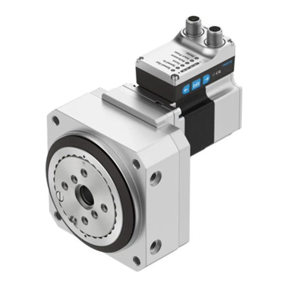
Fig. 2: Product design ERMS
Electrical connections, display and operating components (HMI)
1
Fig. 3: Electrical connections, display
5
NOTICE
Unexpected and unbraked movement of components
• Secure moving components for transport.
Transport conditions and storage conditions
– Store and transport the product in its original packaging.
– Store the product in a cool, dry environment protected from UV and corrosion.
Keep storage times short.
– Store product in areas where it is not exposed to oils, greases and degreasing
vapours.
6
6.1
WARNING
Risk of injury due to unexpected movement of components.
The drive can move freely in the voltage-free state. This can cause unexpected
movements of the connected mechanics and crush parts of the body.
• Bring moving parts of the mechanical system into a safe position.
6.2
1. Open packaging.
System overview
Product design
2
3
4
5
6
7
8
9
10
2
3
4
5
6
7
8
and operating components
(HMI)
Transport
Assembly
Safety
Unpacking
PELV fixed power supply for load
1
voltage
2
PELV fixed power supply for logic
voltage
3
Application software
4
PC or laptop
5
Controller or IO-Link master
Rotary drive unit ERMS
6
1
Hollow shaft for energy through-feed
2
Rotary drive ERMS
Product labelling
3
Controller housing
4
Integrated drive EMCS-ST
5
Warning symbol "Attention! Hot sur-
6
face"
7
Rotating plate
8
Thread and centring hole for attach-
ment components
Thread and centring hole for direct fas-
9
tening
10
Thread for direct fastening
LED display menu (Speed Out, ...,
1
Demo)
2
LED parameter display
3
LED C/Q
4
Connection for load voltage [Power]
5
Logic voltage connection and digital
I/O or IO-Link connections [Logic]
Pushbutton actuator (right arrow)
6
Pushbutton actuator (Edit)
7
Pushbutton actuator (left arrow)
8
Advertisement

Related Manuals for Festo ERMS


Summary of Contents for Festo ERMS
- Page 1 – Observe the tightening torques. Unless otherwise specified, the tolerance is and operating components ± 20%. (HMI) Intended use The rotary drive unit ERMS is used as intended for the rotary movement of Transport payloads between two end positions. NOTICE Training of qualified personnel...
-
Page 2: Installation
2. Place the mounting attachments on the support points. 3. Tighten retaining screws. Observe max. tightening torque and max. screw-in depth. For additional information, contact your local Festo Service. Tab. 5: Overview of attachment component Direct fastening Mounting via thread (bottom,... - Page 3 Updating device data (only via IO-Link) • Firmware update • Updating parameter set • Data backup (Data Storage) è "Integrated drive EMCS" instruction manual è www.festo.com/sp Commissioning: DIO operation (digital I/Os) Preparation: 1. Check mounting of the drive system. 2. Check wiring of the power supplies and the "DI/DO" digital inputs and out- puts at the [Power] and [Logic] connections.
- Page 4 5. Parameterise operating modes via HMI interface: Dimension reference system Basic parameters for point-to-point operation with and without press function The correct positioning of the drive requires a defined dimension reference or manual operation (demo) system. – Velocity "Speed Out" Rotary drive system –...
- Page 5 Homing after a restart as a function of the positioning task Sequence – Mov : force-controlled movement against mechanical stop "Mech " – Mov : position-controlled movement to the reference end position "Ref" – Travel to the target position as a function of the positioning task –...
-
Page 6: Point-To-Point Operation
If automatic storage is activated (0x0109.0 = true, default), parameter changes in the device data (= data storage parameters è "Integrated drive EMCS" instruction manual è www.festo.com/sp) are made automatically and perma- nently saved in the flash memory. Exceeding the maximum permissible 100,000 write cycles results in irreparable damage to the flash memory and the device, e.g. - Page 7 Tab. 13: Fault clearance 11.2 Repair Repair or maintenance of the product is not permissible. – Send product to Festo repair service. – Replace with an identical product è www.festo.com/spareparts. Fig. 8: Display of diagnostic messages (example) Replacement Error Description...
- Page 8 4) The torque acts on the stop for £100 ms 5) Unchangeable parameter. 6) Distance (MechIn – LimIn or MechOut – LimOut) Tab. 14: Technical data ERMS Size Materials Note on materials...
Need help?
Do you have a question about the ERMS and is the answer not in the manual?
Questions and answers