Table of Contents
Advertisement
Quick Links
EPCS-BS
Electric cylinder unit
Operating instructions
8151724
2021-02b
[8151726]
Translation of the original instructions
© 2021 all rights reserved to Festo SE & Co. KG
IO-Link® is a registered trademark of its respective trademark holder in certain
countries.
1
About this document
1.1
Applicable documents
All available documents for the product è www.festo.com/sp.
Type
Product
EMCS-ST
Integrated drive
EPCC-BS
Electric cylinder, with spindle drive
EAMM-A
Axial kit
NEFC-M12G8-0.3-M12G5-LK
Adapter
Tab. 1: Applicable documents for the product
1.2
Product version
This documentation refers to the following datasets:
– Firmware version of the integrated drive from "v19.0.4.107_release"
– IO-Link device description file (IODD) from V1.2.6
When using a different firmware version, check whether a corresponding version
of the documentation is available è www.festo.com/sp.
2
Safety
2.1
Safety instructions
– Observe labelling on the product.
– Prior to assembly, installation and maintenance work: Switch off power supply,
ensure that it is off and secure it against being switched back on.
– Store the product in a cool, dry, UV-protected and corrosion-protected environ-
ment. Ensure that storage times are kept to a minimum.
– Observe tightening torques. Unless otherwise specified, the tolerance
is ± 20 %.
2.2
Intended use
The electric cylinder unit EPCS-BS is intended for linear movement of payloads or
as a drive when external guides are used between two end positions.
2.3
Training of qualified personnel
Work on the product may only be carried out by qualified personnel who can
evaluate the work and detect dangers.
The qualified personnel have knowledge and experience in dealing with electric
drive systems.
3
Additional information
– Contact the regional Festo contact if you have technical problems
è www.festo.com.
– Accessories and spare parts è www.festo.com/catalogue.
4
Product overview
4.1
Scope of delivery
The following components are included in the scope of delivery:
– Electric cylinder unit EPCS-BS
– Instruction manual for the electric cylinder unit EPCS-BS
– Adapter for IO-Link operation (optional accessory)
è www.festo.com/catalogue
4.2
The electric cylinder unit converts the rotary motion of the mounted motor into a
linear motion of the non-rotating piston rod. The lead screw converts the torque
of the motor into a feed force. The linear movement of the piston rod is guided by
the guide in the guide ring.
4.3
Festo SE & Co. KG
1
Ruiter Straße 82
73734 Esslingen
2
Deutschland
+49 711 347-0
3
www.festo.com
4
5
6
Fig. 1: System overview EPCS-BS
Items 1 ... 5 are not included in the scope of delivery.
4.3.1
1
Table of contents
Manual
Operating instructions
Assembly instructions
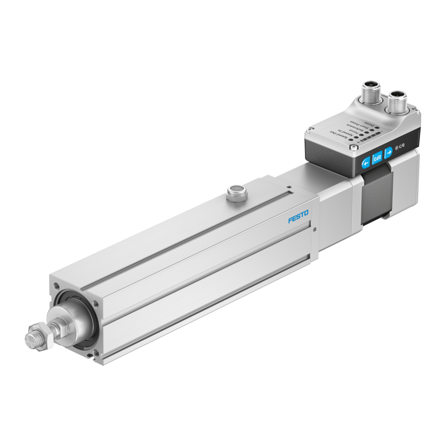
Fig. 2: Product design EPCS-BS
Assembly instructions
Electrical connections, display and operating components (HMI)
1
Fig. 3: Electrical connections, display
5
NOTICE
Unexpected and unbraked movement of components
• Secure moving components for transport.
•
Take product weight into account è 13 Technical data.
6
WARNING
Risk of injury due to unexpected movement of components.
The drive can move freely in the voltage-free state. This can cause unexpected
movements of the connected mechanics and crush parts of the body.
• Bring moving parts of the mechanical system into a safe position.
•
Mount product è "Electric cylinder EPCC-BS" instruction
manual è www.festo.com/sp.
7
WARNING
Risk of injury due to electric shock.
• For the electrical power supply with extra-low voltages, use only PELV circuits
• Observe IEC 60204-1/EN 60204-1.
Function
System overview
Product design
2
3
4
5
6
7
2
3
4
5
6
7
8
and operating components
(HMI)
Assembly
that guarantee a reinforced isolation from the mains network.
PELV fixed power supply for load
1
voltage
PELV fixed power supply for logic
2
voltage
3
Application software
4
PC or laptop
Controller or IO-Link master
5
6
Electric cylinder unit EPCS-BS
Electric cylinder EPCC
1
2
Sealing air connection with filter
element
3
Axial kit EAMM
Product labelling
4
5
Integrated drive EMCS-ST
6
Controller housing
Warning symbol "Attention! Hot
7
surface"
1
LED display menu (Speed Out, ...,
Demo)
LED parameter display
2
3
LED C/Q
4
Connection for load voltage
[Power]
Logic voltage connection and dig-
5
ital I/O or IO-Link connections
[Logic]
Pushbutton actuator (right arrow)
6
7
Pushbutton actuator (Edit)
8
Pushbutton actuator (left arrow)
Advertisement
Table of Contents

Related Manuals for Festo EPCS-BS


Summary of Contents for Festo EPCS-BS
- Page 1 Transport Intended use NOTICE The electric cylinder unit EPCS-BS is intended for linear movement of payloads or Unexpected and unbraked movement of components as a drive when external guides are used between two end positions. • Secure moving components for transport.
- Page 2 • After the power supply is switched off, let the device cool down to room temperature. Update device data (only via IO-Link) • Update firmware • Update parameter set • Data backup (Data Storage) è "Integrated drive EMCS" instruction manual è www.festo.com/sp Commissioning: DIO operation (digital I/Os) Preparation:...
- Page 3 1. Check the mounting of the drive system. Linear drive system 2. Check wiring of the power supplies and the "DI/DO" digital inputs and out- puts at the [Power] and [Logic] connections. : reference end position (reference point for Lim , Lim , Pos , Pos...
- Page 4 If automatic storage is activated (0x0109.0 = true, default), parameter changes in the device data (= data storage parameters è "Integrated drive EMCS" instruction manual è www.festo.com/sp) are made automatically and perma- nently saved in the flash memory. Exceeding the maximum permissible 100,000 write cycles results in irreparable damage to the flash memory and the device, e.g.
- Page 5 0x... yellow light Error Common device error or … 0x1000 unlisted errors Remedy red light – Contact Festo 0x000F t monitoring output stage 0x1805 (15) error limit Remedy – Point-to-point operation with press function and intermediate position (IO-Link only) 0x0016...
- Page 6 The product can be repaired or maintained. Tab. 8: Technical data EPCS-BS – Spare parts and accessories è www.festo.com/spareparts. – Replace with an identical product è www.festo.com/catalogue. Replacement Replace drive system 1. Save the application parameters to the IO-Link master è "Integrated drive EMCS"...
Need help?
Do you have a question about the EPCS-BS and is the answer not in the manual?
Questions and answers